Final Assembly
page 2 (2011)
Page 1 - The Cub
Project
Page 2 - Fabric
Page
3
- Firewall Forward
Page
4 - Firewall Forward (page 2)
Page
5 - O-320
Overhaul (for the Cub)
Page 6 -
Final Assembly (2010)
Page
7 - Final Assembly (2011 page 2)
Page
8 - Final Assembly (2011 page 3)
Page 9 - Completed
Aircraft
Page 10 - Later Updates and
Modifications
Page 11 - MOGAS vs
Composite Fuel Tanks
POH
for Scott Grizzly Cub N143W
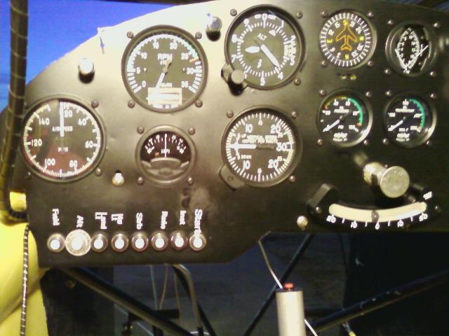
Jan 21, 2011 - With the second O-200 completed and the O-320 for
the
Cub
torn down, I'm back to
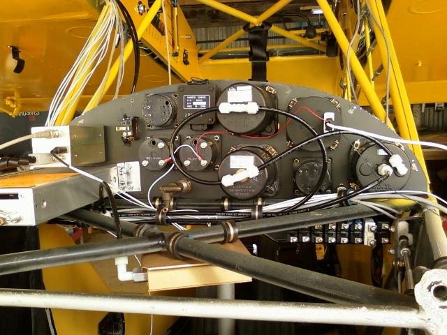
working on the plane itself. Today I completed the Pitot and
Static
plumbing
for the instruments.

January 22, 2011 - The same picture taken the next day. The
transponder and encoder wiring harness is now
completed. One might also notice that the wiring running up
either side of the
windscreen posts is now enclosed
in spiral wrap. It was an interesting day today. I
powered up some of the
systems
individually. The strobes
worked well. The right nav light was out. I finally found a
wire that had
pulled
out of a molex connector, so
replaced the molex pin. The Whelen tail light apparently wasn't
built to the same standards as
was used for the
last 80 years, so I had to modify the rudder and tail light to marry
them together. As
soon
as I applied power to
the landing light circuit the WigWag control module went up in smoke.
I verified several
times
that it has been wired
correctly. I have an identical unit in my other plane and have
never had a problem with it.
I
guess
we'll call this an
infant mortality. We'll see what Eric at Parihelion Design says.
Eric at Parihelion now recommends an in-rush current limiter for 100W
lights, which he offered to ship me for free.
He also asked me to check my wiring once more to make absolutely sure
it is correct. I sent him some $$ via Paypal
to cover the current limiters and for a second set of current limiters
for my other plane. He is shipping me a new WigWag
unit. If I find that I made a wiring mistake, I'll send him
another $78 to cover the WigWag unit. Hey, on occasion, I do
make mistakes. :o)
January 29, 2011 - Added the in-rush filters to the landing lights per
Perihelion's recommendation. Installed
the new WigWag module today. It promptly went up in smoke as
well. Once again, the wiring was verified
to be correct. It took hours of troubleshooting, but the
problem
was finally discovered. It turned out the little
lights that backlight the switches when in the on position only measure
.2 ohms, which would make an initial
transient in-rush current of 60 amps, plus the inrush current of the
landing
lights themselves, which measure .5
ohms cold to make them 24 amps. OK, so that's an 84 amp surge for
a
microsecond or two when one of the
landing lights flashes on with the WigWag unit, which will easily
destroy the FETs in
the unit. Now I have to
order another. :o(
Feb 4, 2011 - Installed the third WigWag unit. It works as
expected. It really was the transient amperage spike
to the backlighting in the switches that was blowing up the WigWag
modules. I unplugged the grounds from the
backlighting in the switches to disable the backlighting. That's
what I get for buying crappy AutoZone switches.

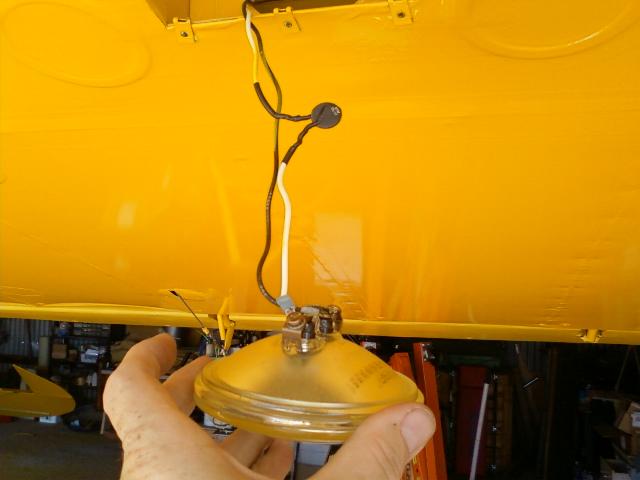
Landing lights sans wigwag module.
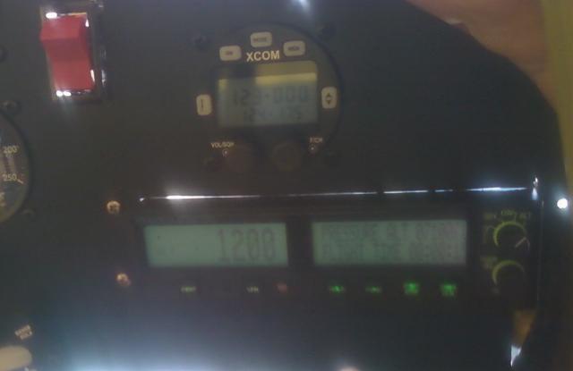
Jan 23, 2011 - Electrical testing continued today. The radio
and
the remote head for the radio came up OK.
It receives well, but just transmits a hum. I suspect the mic
wiring is incorrect. I remember when I was wiring
it, I thought the directions for the mic wiring seemed a bit odd.
That was
probably
my interpretation of the wiring
diagram. It's the same from both inputs, so I'd bet I'll just
have to move a wire on
the mike jacks.
The transponder didn't come up. I found that the edge
connector
at the back of the mounting tray wasn't deep
enough into the back of the tray for it to make contact on the edge.
A trip to the hardware store for longer screws
and some nuts to use as spacers, and it now makes good contact.
The altitude display is correct (7100 ft), so I
must have got the encoder wiring correct.
Jan 24, 2011 - As expected, the mic wiring was incorrect. I
now
get voice transmitted and the intercom works,
but the hum is still present when it transmits. It appears to
be
a grounding issue that I'll have to sort out.
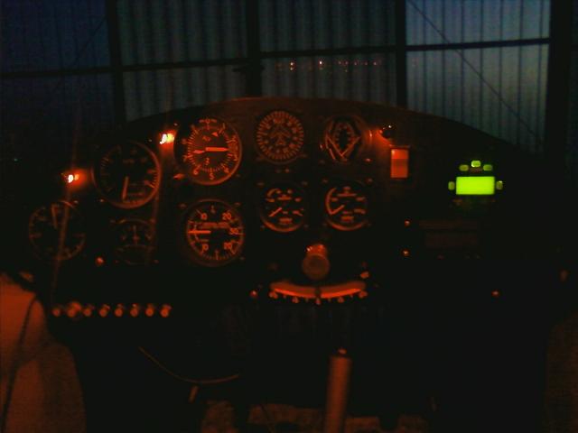
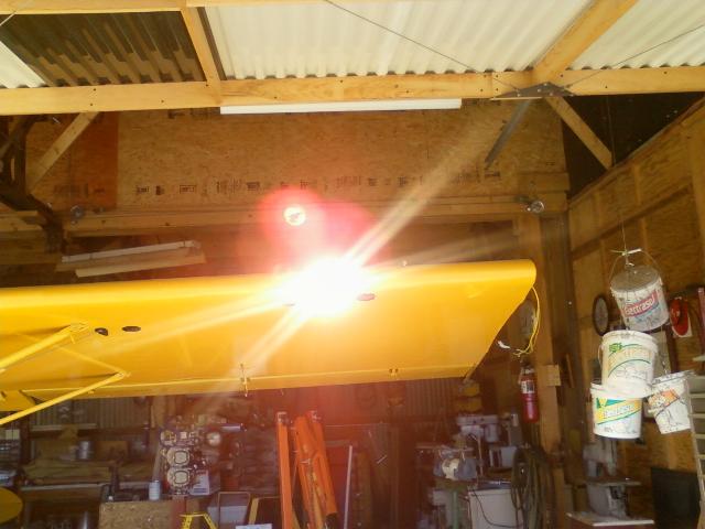
1/25/2011 - Panel lighting.
I rang out the radio wiring this evening. It is wired
correctly.
The source of the feedback in the radio is a mystery,
although one headset is much worse than the other and the problem
follows the headset.. I recall that I had some
wierdness with these Lightspeed QFR headsets with the radio in my
Tomahawk as well, so it may be a headset
problem, which would be disappointing and expensive. I'm
going to
ask for another set of eyes to check this over
for me, and will test with another headset as well.
1/26/11 - The source of the radio feedback was discovered. I
put
a longer antenna lead on the radio and moved
the antenna few feet further away. The noise went away.
I
had the antenna laying on it's side on top of the wing
for testing with no ground plane and nothing metal between it and me.
It was inducing feedback into the radio and /or
headsets, and also was even causing the LED backlighting in the
transponder to light up. After moving the antenna,
all symptoms went away. Of course we know that these antenna
are
somewhat directional as well, and with the
antenna laying on it's side about a foot above my head, I would have
been right in the primary lobe where the signal
was strongest. I also trimmed the gain on the mics of the
headsets to balance them better. This makes it quite clear
that I had better test my antenna location before I drill any mounting
holes!
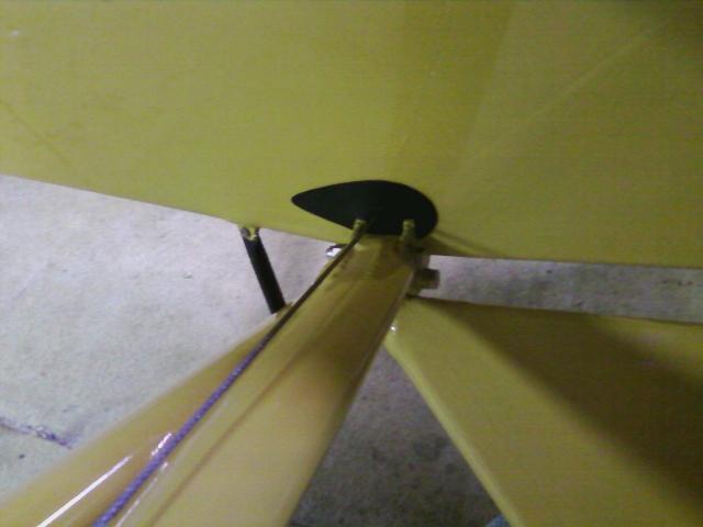
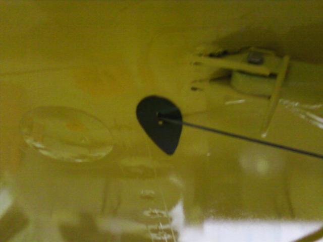
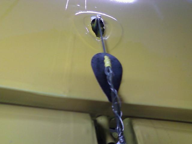
January 28, 2011 - Added the rub patches to the fabric where the cables
pass through the fabric.
January 20, 2011 - I finally got the labels on the breakers.
I
can't say that I'm happy with the way it turned out,
but they are there for now. Since they are vinyl, I can always stop in
at my buddy's
shop
in Iowa to peel these
off and install a better set.

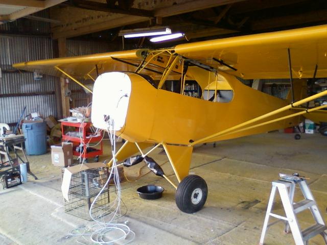
OK, now the panel wiring is completed as, are the primer
lines.
I still need to install a "Alt Inop" light in the
panel for the alternator, but otherwise it is complete and ready for
the boot cowl.
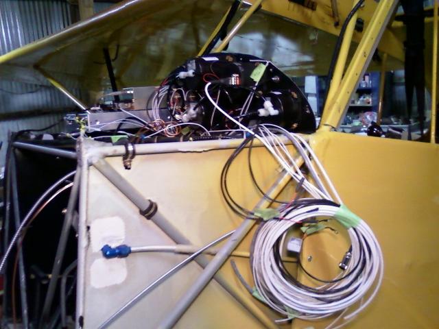
This wiring that's all rolled up here is all the wiring that need to go
through the cowl to the engine compartment.
February 5, 2011 - Today's project was the brakes. Slave
cylinders were taken apart, honed and new O-rings
installed. Torque pins had the rust polished off and were
lubricated. I ran the NyloSeal brake lines from the
back of the gear leg up to the master cylinders. I'll fill
with 5606 hydraulic tomorrow. I found that the bearing
and races were all showing rust. That was a case of sticker
shock. $300 for 4 bearings and races using the
Cleveland numbers. I cross referenced the Timken bearing
numbers and was able to find them for $200 from
SkyGeek. Still seems a bit steep to me, but that was the best
deal I could find.

February 6, 2011 - I painted the throttle covers yesterday
and added the vinyl lettering today. I did the other
graphics below as well. I also repainted all the window and
door mounting hardware as it had a nice coating
of yellow overspray from when I painted the plane last summer.
I should be ready for the boot cowl, doors
and windows in the next week. The picture above is the
throttle for the rear cockpit.
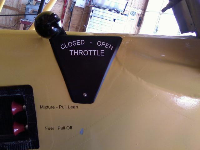
The front throttle along with the mixture and fuel valve.
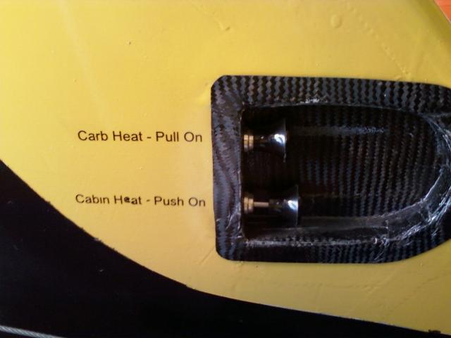
Carb and cabin heat on the right side of the cockpit.
February 10, 2011 - I've been really struggling with where to put the
battery. The front of the firewall is very
convenient, but the SuperCub drawings all show the battery mounted
behind the back seat. I made numerous
lay outs of the battery mounting on the firewall, but really didn't
come up with anything I liked. With the big engine
and the metal prop, I decided the aft weight might be a good thing.
Last night I routed that heavy #2 battery
cable that I was hoping not to run the length of the cockpit.
It and the master relay lead are wrapped in plastic
spiral wrap for abrasion resistance and will get some adel mounts in
various places along under the floorboard.
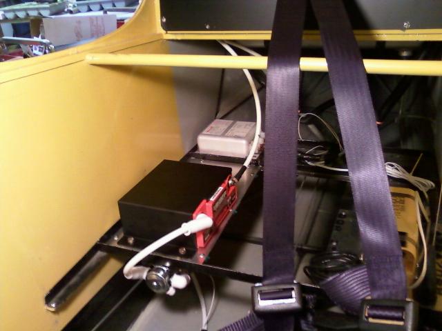
Feb 12, 2011 - Fabricated and attached a tray to go under the baggage
bag for the Odyssey battery. Also
mounted the master relay under the tray.

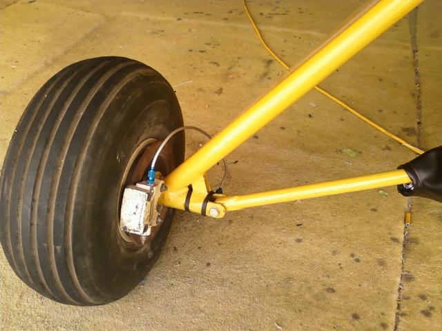
Feb 12, 2011 - Wheel bearing problems. I pulled this wheel
last weekend and saw that the bearings and races
were badly pitted. I put the wheel back together, then looked
up the bearings and races via the Cleveland parts
in the Aircraft Spruce catalog. $300 for 4 bearings and
races! OK, Chief shows a cross reference to the Timken
part numbers. The best price I could find for 4 13836-20629
races and 13889-206329 bearings was $200 from
SkyGeek. I went to change them out and found that the new
bearings and races were significantly different from
the ones found in the wheels. The ones in the picture are
about
1/4" wider with larger rollers. It turns out that the
left bearings and races were OK, so I repacked and re-installed them.
I punched the races out of the right wheel
and found that the races are stamped Timken LM29710 and the bearing is
LM29749. Both parts are commonly
available at autoparts stores and are used as a differential bearing in
everything from a VW to a John Deer tractor.
I was able to buy two sets of bearings and races for $28 from Rock Auto.
Feb 13, 2011 - The boot cowl is finally installed... hopefully for the
final time. The instrument panel is now
attached to the boot cowl and all the wiring is pulled through the
firewall. This is a major step towards flying.
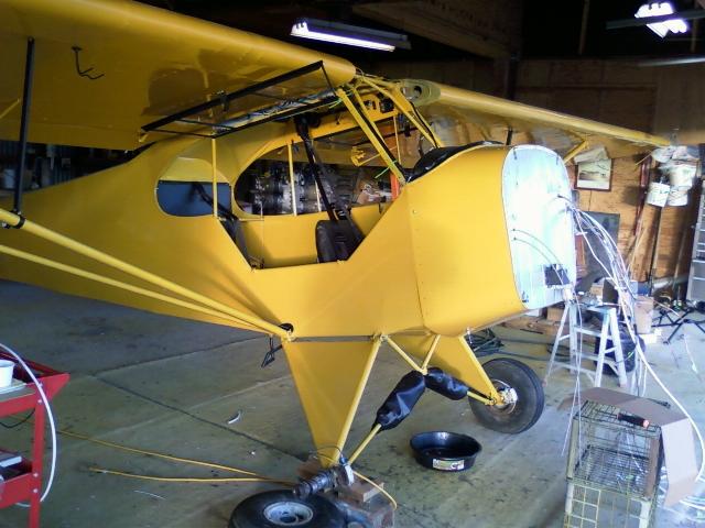
Other side of the boot cowl. Note the transponder antenna
mounted to the bottom of the boot cowl.
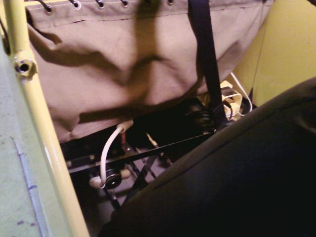
Feb 15, 2011 - Tonight I finally got to install the back seat.
This is a picture of the battery and master relay
as they sit behind the back seat and under the baggage bag.

The back seat finally in place. It sits substatially higher
than the front seat, which seems a bit low to me.
Note: During early test flying, the front seat mounts broke. I
have no idea what they were welded with, but
it wasn't welding rod. Anyway, I built a new seat frame and
raised it 1 1/2". It is much more comfortable to
sit in and gives much better access to the master cylinders for
maintenance as well room for the rear seat pilot
use the rudders and brakes.
Page 1 - The Cub
Project
Page 2 - Fabric
Page
3
- Firewall Forward
Page
4 - Firewall Forward (page 2)
Page
5 - O-320
Overhaul (for the Cub)
Page 6 -
Final Assembly (2010)
Page
7 - Final Assembly (2011 page 2)
Page
8 - Final Assembly (2011 page 3)
Page 9 - Completed
Aircraft
Page 10 - Later Updates and
Modifications
Page 11 - MOGAS vs
Composite Fuel Tanks
POH
for Scott Grizzly Cub N143Ws