Marquart Charger O-360-A1A Engine Overhaul
Engine overhaul
Electronics/Electrical
Fuel System
Trim System
Fabric Recover
Items #4 & #5 from the rebuild page:
Top overhaul of the engine and replace the tired magnetos. This is a strong running
engine, but also uses a lot of oil despite the fact that it really
doesn't leak. That says it has either oil ring or valve guide
issues. I bought new Superior cylinders and some 10:1 compression
pistons for it, so will add a bit of HP in the process.
This was supposed to be a simple top overhaul of the engine on my
biplane, but once I got into it, things kind of snowballed. So, I
created a separate page for the engine. This engine is a prime
example of why, when I shop for a plane, I always look for one in need
of an overhaul. Invariably, the first time I open up the engine,
I find all kinds of things that give me heartburn, to I inevitably end
up doing a complete major. So, with this engine completed, I will
have majored the engines on all three of my current planes.
11/8/2024 - I removed the cowling, baffling, and ultimately the top end
on the engine with a plan to do just a top overhaul on the engine.
O-360-A1A. Easy Peasy. While this engine wasn't an oil leaker, it sure is filthy looking.
I thought I had seen most everything in these engines. But, I have
never torn down a Lycoming that used drilled rod bolts and castellated
nuts. The small Continentals do, but not Lycomings. I guess they did
use them back in the 60s, and it's likely the previous overhaul re-used
the rod bolts and nuts. Perhaps that was acceptable in 1969.
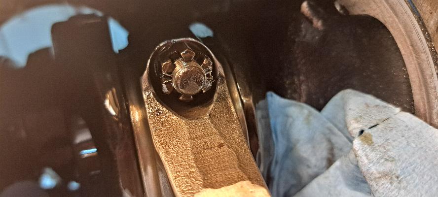
It's not anymore. Rather than cotter pins,
this had roll pins driven into the holes in the rod bolts, then the
ends of the roll pins hammered
down to spread them out. Now that was a royal pain to get out as
each roll pin had to be drilled with my angle drill to remove the ends
of the roll pins. I broke 3 of the short angle
drill screw-in bits, so that was about $15 worth of bits that I trashed
getting those roll pins out.
11/9/2024 - My plan was to send the connecting rods to my buddy in
Santa Fe to have them balanced, then put the engine back together again
as I have another engine project arriving later this month. Well... That plan went down the toilet this morning.
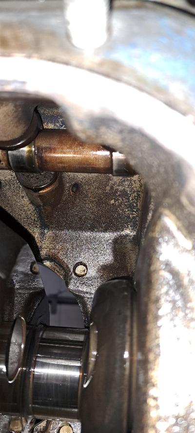
What is that I see? Corrosion on the cam follower? That
corrosion will lead to cam spauling, so my top overhaul just turned
into a major overhaul. The cam does not appear to be damaged yet, but I won't know that for
sure until I get it out to inspect. Most of the cam followers are showing varying degrees
of corrosion, so I expect they will all need to be replaced.
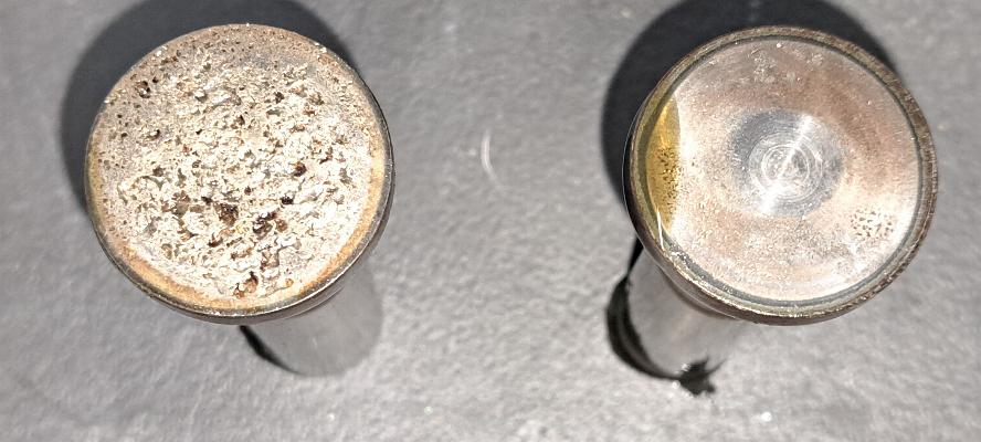
Some folks expressed that they didn't see the failing cam follower
(tappet, lifter body). Here's a photo of two of the cam
followers from the engine. All the pitting on the face of the one
on the left will act like a machine tool to grind away the lobes from
the cam shaft. The cam follower on the right shows some mild
pitting and could probably be reground. I chose to replace them
all rather than using a mix of new and reground.
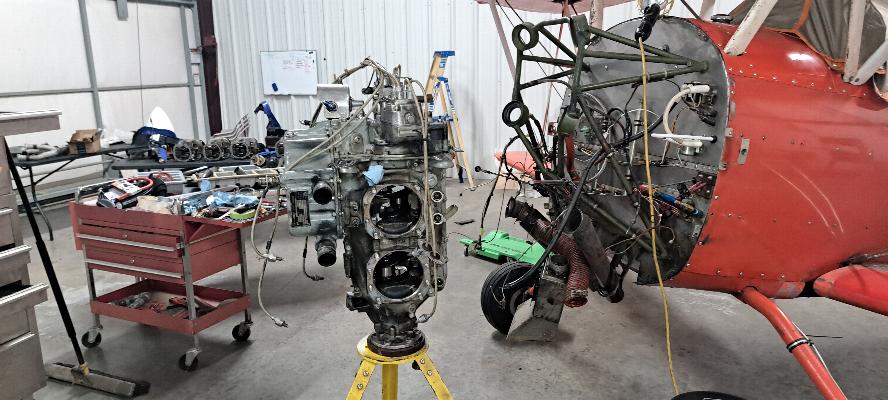
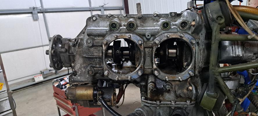
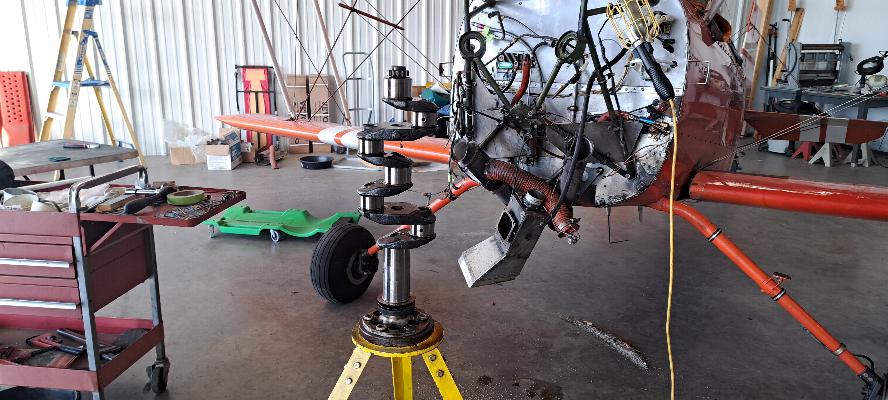
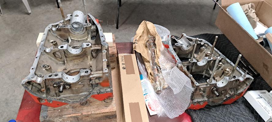
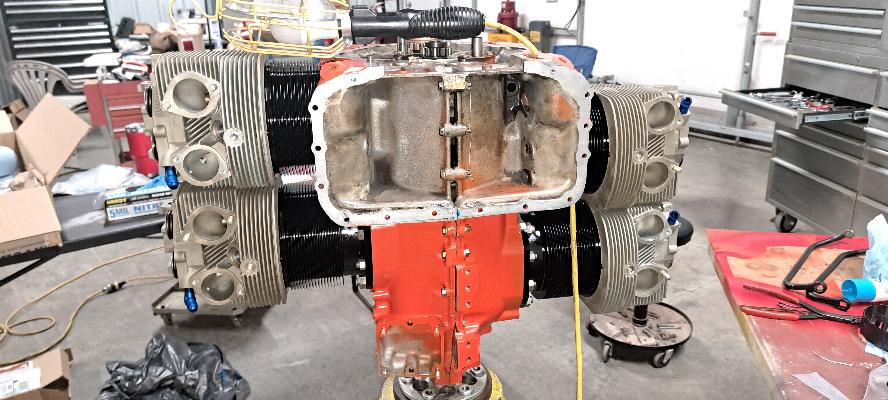
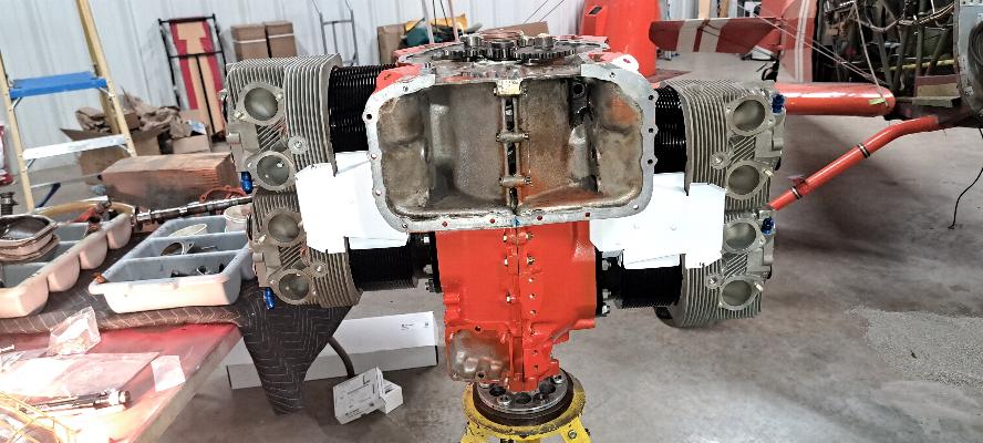
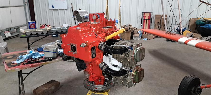
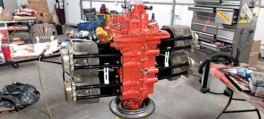
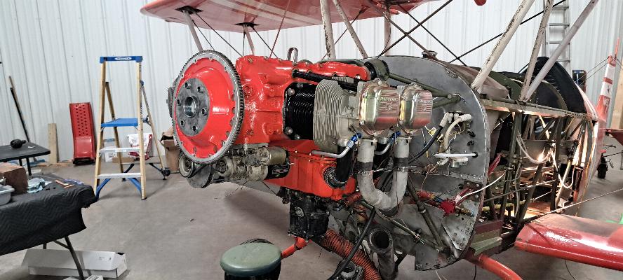
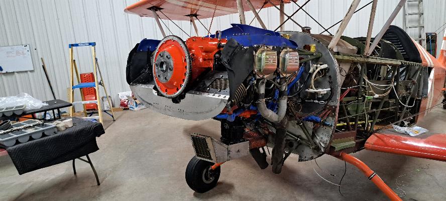
Here we are with the engine off the airframe. I'll split
the case this week and start cleaning parts. I should get
everything cleaned and put away, or prepared to go to the machine shop just in time for the other engine
(angle valve 200 hp IO-360) to arrive. The IO-360 has a cracked
case, but is also due for Major Overhaul as well, so it's going to be a busy shop for a while.
11/11/2024 - Veteran's Day. I did my time for the country. Did you?
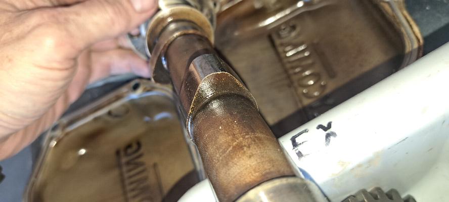
A rounded intake lobe above, and pitted cam lobe below. Other
lobes had more of the same. This cam goes in the trash.
I need a camshaft and 8 cam followers. The rest is cleaning up good. The
mains on the crankshaft and the rod pins are nice and smooth and
measure to new specs. I'll still polish them before engine assembly.
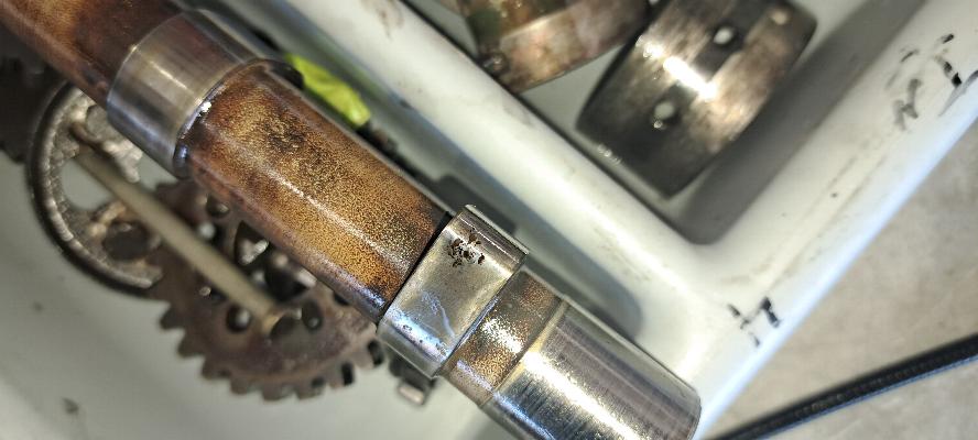
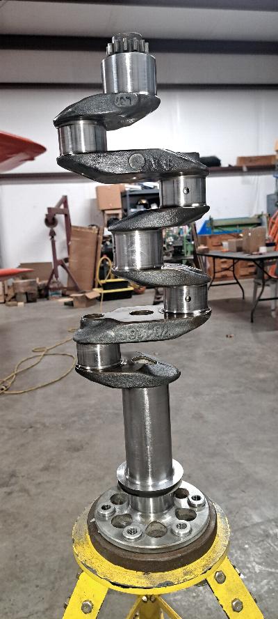
11/12/2024 - I can't tear the engine down any further than this.
I have a bit of a delima with this crankshaft. It has some
corrosion pitting in an area that doesn't touch the bearing surfaces
(actually right between the two supporting surfaces of the front main..
But, the bearing surfaces of the crank look really good and mic
out to new specs. Never-the-less, the pitting is there. If
I send this crank in to a machine shop, the will grind it down within a
few thousandths of it's life or condemn it all together as a CYA move. I could spend $8500 for a new
crank, but I am also fully confident that this crank will be fine as
it is. I'm going to defer the decision until I get a chance to
polish the crank. Then we'll see how things look. And, of
course, this is an Experimental engine built for an Experimental
Aircraft, so I have a lot more leeway in my decision making.
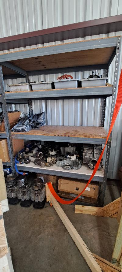
The engine is all packaged up and put away on the shelves to make room
for the IO-360 that should arrive for teardown this weekend.
Despite decent compressions, this engine has always had a high oil
consumption (1 qt to 4 hrs) and the oil would turn very dark within an
hour or two of oil change. When I opened it up, this engine was
filthy inside. Not sludge, but just a dirty grime that seems to
be baked into the porous cast aluminum surfaces. My expectation
is that it is from excessive blow by in the exhaust valve guides, but I
haven't pulled any valves yet to confirm. But the insides of this
engine was thoroughly coated with a layer of black grunge that had to
be buffed off with a wire brush.
Update. The valves had some corrosion in the faces as did the
seats. That all ground out just fine. The valves and guides
all met new spec, so weren't replaced. The cylinders showed some
significant
corrosion pitting in the lower part of the cylinders and were honed to
clean them up. I suspect the pitting in the cylinders was leading
to significant blow-by causing the high oil consumption and the filthy
oil and interior.
11/21/2024 - After spending the last few days tearing down, cleaning and packaging up an IO-360 from another plane, I'm back to my engine again.
The crank journals measured to new spec and looked to be in really good
shape. There was some minor corrosion pitting, but it mostly
disappeared when I polished the crank. After discussion with
another mechanic with 50+ years in the overhaul business, we agreed that
the pitting found was inconsequential, so chose to polish the crank and
re-run it as it is.
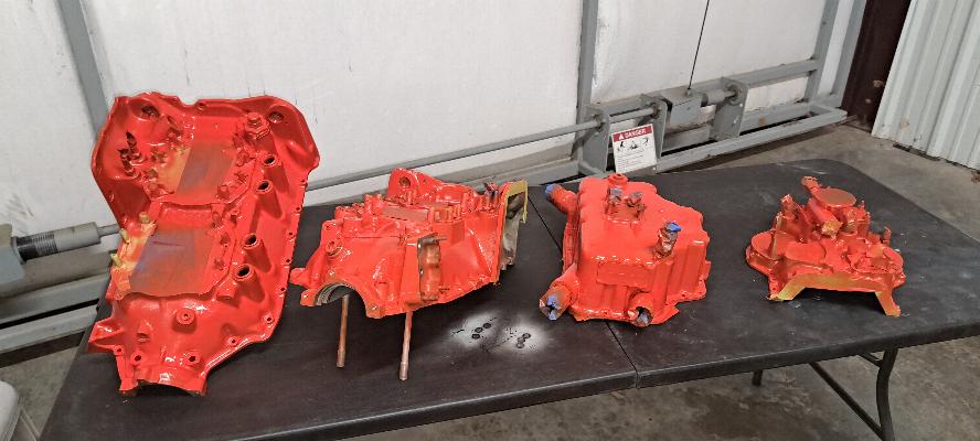
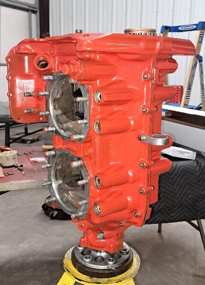
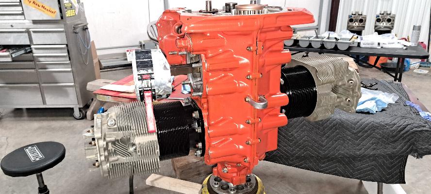
I got the case halves, oil pan, and accessory case out and cleaned on
them a bit more, then masked and painted orange to go with the Orange
Crush paint scheme that I'll be keeping on the plane.
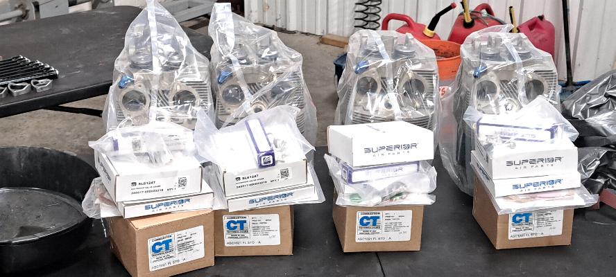
I also have 4 new Superior cylinders ready to go along with 10:1 compression pistons from Combustion Technologies.
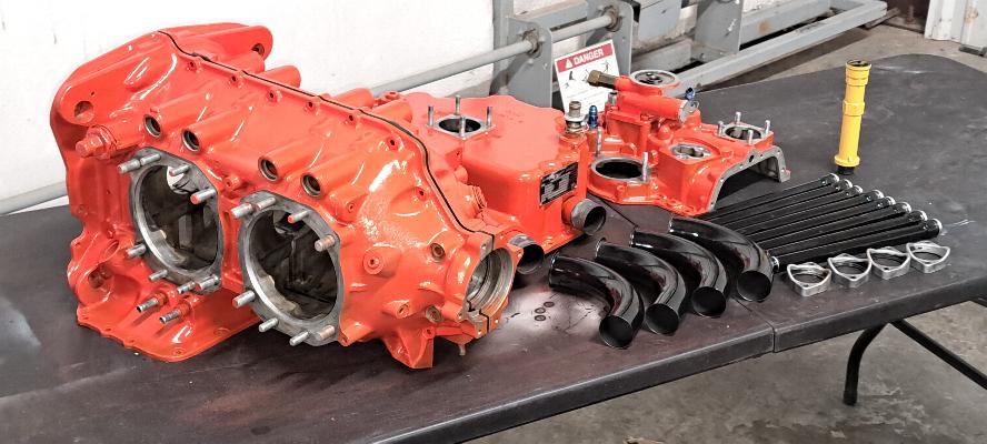
Case parts after painting along with freshly painted intake tubes and
pushrod tubes. I'm still waiting for my connecting rods and wrist
pins to be delivered, otherwise I'm ready to start going together with
the engine. I'll have to get pictures later, but I also pulled
the plug out of the crank and did the Lycoming SB505 inspection.
I don't think that had ever been done as it must have had close
to 3/8" of sludge in the front of the crank. I'll go ahead and
treat the crank bore with a Urethane metal primer per SI-505 before I
install the crank.

11/24/2024 - Lycoming SI-505 compliance... sort of. This was
under the old FAA A.D. 98-02-08. It had clearly never been
accomplished as I found about 3/8" of sludge coating the inside of the
crank bore. The AD requires pulling the front plug out of the
crankshaft. I do this by drilling the plug and running a sheet
metal screw through the plug, then attach to the plug with a slide
hammer. It comes out relatively easy. Once the plug is out,
scrape all the compacted sludge out of the crank bore. Since this
crankshaft is out on the bench, I was able to clean it thoroughly using
cleaners I would not have normallly put into an engine that was
assembled. Upon inspectiong, I found no pitting inside the crank
bore. These bores are pretty rough from the original tooling from
boring, but there was no pitting.
An interesting side note: This crankshaft was once used with a constant
speed prop. Typically for a fixed pitch prop, the plug in the
back of the crank bore is missing. That plug is only there if the
engine is going to be used with a constant speed prop. When
converting it for use with a fixed pitch prop, a hole is drilled in the
plug, then a plug is staked into the front of the crank bore. The
early 180 hp Mooney's used the carburated O-360-A1A, so it is likely
this engine was once flying around on the front of a Mooney M20C.
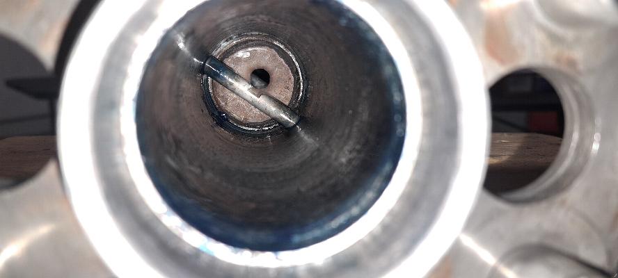
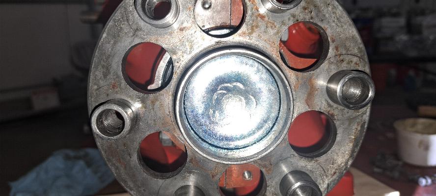
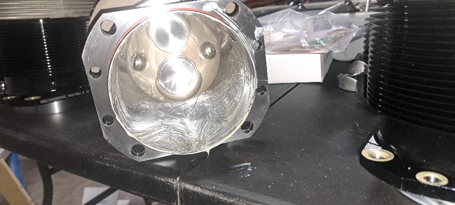
For those not familiar with how a constant speed prop is
controlled, the oil tube you see inside the prop bore has a hole
slotted into the side of the tube. The prop governor transfers
oil under pressure to the center of the front main bearing between the
two bearing supports where the crank rides. That oil flows
through the holes in the crankshaft into this tube and fills the bore
of the crankshaft with oil. That oil is pressurized to force oil
pressure into the prop hub to increase the pitch of the propeller.
The oil pressure is allowed to bleed off by the prop governor to
reduce the pitch of the prop. The constant speed propellor hub
slides into the front bore of the crankshaft with an O ring in a groove
on the prop hub to seal the prop hub to the front bore in the
crankshaft.
The Service Instruction calls for coating the inside of the crank bore
with Urethabond 104, which is a urethane based metal primer. I
was going to order some, but found it cost roughly $170 for a cup.
So, I looked up an equivalent Urethane primer. In this
case, I bought Devcon FL-10, which is chemically equivalent and cost
$42 per cup. OK, call me cheap. This crankshaft will never
be used in a certificated aircraft, so as an Experimental, it is my
option to treat the crank as I see fit. I am more concerned about
ensuring the crankshaft remains unpitted than I am with complying with
the specifications of the A.D. This morning I cleaned the crank
bore again, then acid etched it to prepare the surface to bond to the
Urethane primer. Once it was dry, I coated the inside of the bore
using an acid brush. The Service Instruction only calls for coating
the front 3-1/2" of the crankshaft bore. Typically in a machine
shop, the crankshaft would also undergo a magnaflux inspection for
cracks and a zyglow inspection for a better view of any potential
pitting.
I do have the capability of doing flourescent dye penetrant
testing, but my concern was not really with cracks as this crank had
not suffered any potential damage, and a visual inspection with
magnifier and a bright light showed no signs of corrosion or pitting.
My concern was for inspection for corrosion, then corrosion
proofing the crank bore. So, technically, I did not comply with
SI-505 as far as the sealing of the crankshaft goes when the crankshaft
is overhauled. I also did not overhaul the crankshaft. I
did perform a field cleaning and inspection, which is the part requred
while the engine is in service, then coated the inside bore to seal the
crank to prevent any future corrosion. This process would not be
acceptable for a certificated aircraft, but again, this crankshaft will
never be used in a certificated aircraft.
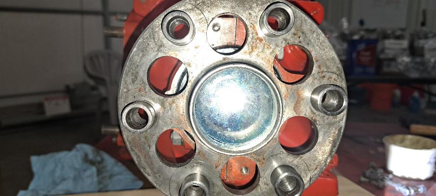
New plug placed into the front of the crankshaft bore. There is
some sealant painted on the inside of the bore around the shoulder
where the plug seats.
Then the plug gets staked with a hammer and punch. Punching in
the center of the convex plug will expand the plug out against the
edges of the crank bore and will hold it in place. I know
Lycoming has a special tool for this. But I've never seen one
fail that was properly staked. I have had one leak that I didn't
punch deep enough to get it to seal.
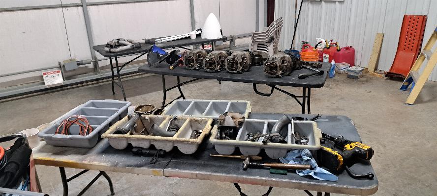
11/25/2024 - Getting the parts laid out to start putting my O-360-A1A
back together again. New bearings in the case. New camshaft
in the wrapper laying between the case halves. I'm flying off to
meet friends for breakfast tomorrow, so will get started on assembly
tomorrow afternoon.
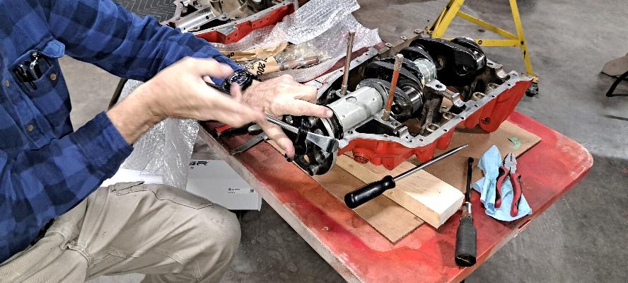
11/26/2024 - I took the morning off and flew to Kingsley in Missouri for
breakfast at the Hangar Restaurant with some friends. Back to it
this afternoon. This photo is installation of the one piece front
seal. I removed the garter spring from the seal and clipped it
back together behind the prop flange, then heated the seal in a cup of
water in the microwave. It was boiling pretty good after 4
minutes, so I stretched it out over the flange using 4 motorcycle tire
spoons. Once it is over the flange, it will shrink right back to
size and you pop the spring into the back side of the seal. I
have done this countless times. It is always a struggle and I am
amazed every time that I can get it done without destroying the seal.
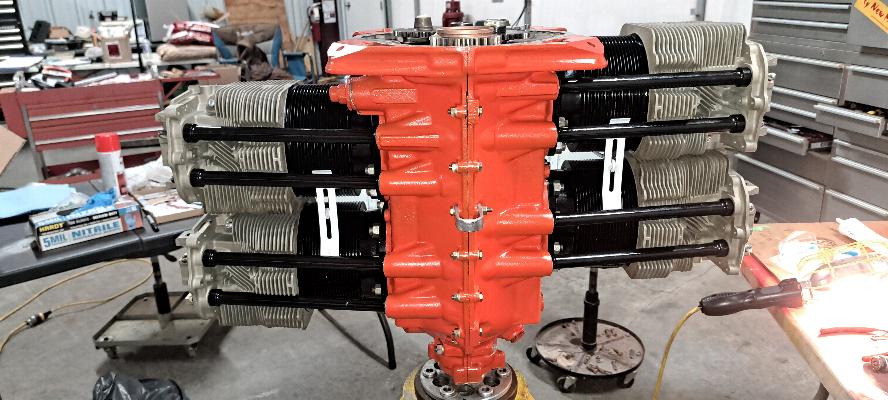
Bottom end of the engine together. The case is just bolted
together with the perimeter bolts snugged up. I'll torque them
all tomorrow. I forgot to install the front plug in the
crankshaft, so might want to take it back off the stand to install that
tomorrow before the engine starts getting too heavy for me to handle by
myself. I try to remember to take pictures as I put things
together, but keep forgetting. I'll get things done, then
suddenly realize that I forgot again to take any photos. (I have things
out of order here as I took the engine off the stand and installed the
plug in the front seen in the photos above.)
11/27/2024 - This morning I spent a lot of time moving all the engine
parts from the other hangar back to this hangar, then sorting and
cleaning parts getting them ready for installation. I also
checked the accuracy of my torque wrenches, then torqued the case
bolts, the front collar of the case, and the back stud that's hidden
under the cam gear.
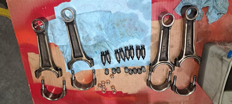
Here, I have the connecting rods laid out with new rod bolts and rod
nuts. They are expensive, but you NEVER re-use rod bolts or nuts
in an aircraft engine. I have also cleaned and tested the hydraulic units for
the lifters and the cups that hold the end of the pushrods as you can
see here in the photo.
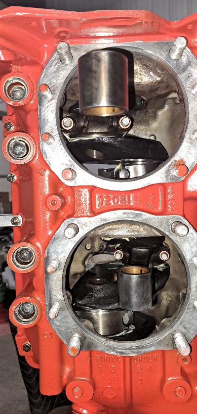
Rods are installed and torqued. If you look into the pushrod
holes, you'll see the cup there on top of the hydraulic units inside
the cam followers, so that part is all together now.
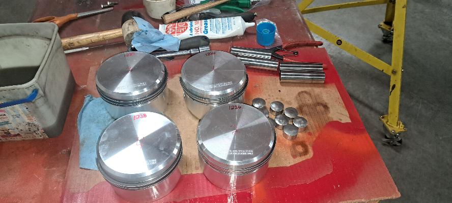
Pistons with rings installed, wrist pins, and the aluminum end plugs
for the wrist pins all ready for installation. This was supposed
to be a perfectly matched set, but you can see they sent me one piston
that is one gram heavier than the two on the right, and another piston
that is two grams heavier. I'll pair the two 1236 gram pistons
together for cylinders 1 & 2, then I took a gram of aluminum off
the boss of the heaviest piston to match the two on the left at 1237
grams to be pairs in cylinders 3 & 4.
New Superior cylinders ready for installation. I cleaned the
cylinders, then greased them thoroughly with Lubriplate Assembly
Lube.Everything that goes in the engine gets a thorough coating of
assembly lube. The only thing that gets a different treatment is
the face of the cam tappets and the camshaft lobes. They get a
coating of black moly grease with zinc to facilitate break in.
Tomorrow is Thanksgiving. I'll take the day to enjoy at home with
Becky while we snooze through some football games and perhaps give thanks
for all the ways we have been so richly blessed in this life. On Friday,
everything is set to install cylinders and continue the build.
I'm ready to get on with it.
11/29/2024 - Hanging the cylinders on the engine. The top left of
the engine is #3 piston all greased up with assembly lube and my ring
compressor clamped around it, ready to slide the cylinder over the
pistons and rings.

All 4 cylinders mounted.
Bottom side. I torqued all the cylinders down here before I
started putting parts on the bottom and all the cylinder base nuts were
easily accessible. FWIW, I go around and check the torque on all
the studs and especially the through bolts 3 times to ensure everything
is torqued correctly. Usually there is some movement; especially
on the throughbolts. It is imperative that they are torqued
correctly.
These are the cylinder base wrenches used to access these nuts.
The top of the wrench has a 1/2" square hole for a 1/2" drive torque
wrench to fit onto them.
Painted and installed the intercylinder baffles. These are
necessary to force cooling air around the bottom of the cylinders for
proper cooling.
Bottom side with the intercylinder baffles installed.
Top side with the baffles in. Also the pushrod tubes are now installed on the top side of the engine.
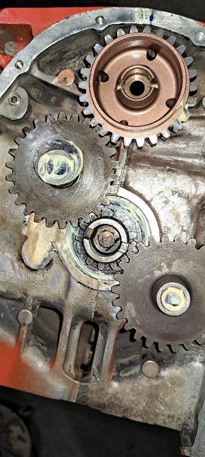
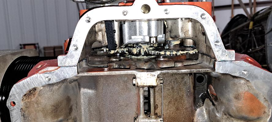
Setting the cam timing. On a Lycoming, there is an idler gear
that sits between the crankshaft (the small gear in the middle) and the
camshaft (the new copper colored gear at the top). Look closely
and you can see timing marks on all of them. The idler in
between has a lobe that bumps the fuel pump and also drives the left
magneto. The idler below drives the right magneto and the prop
governor. This engine doesn't have a prop governor drive installed. It is probably worth noting that all
these gears will get packed with assembly lube before the accessory
case goes on.
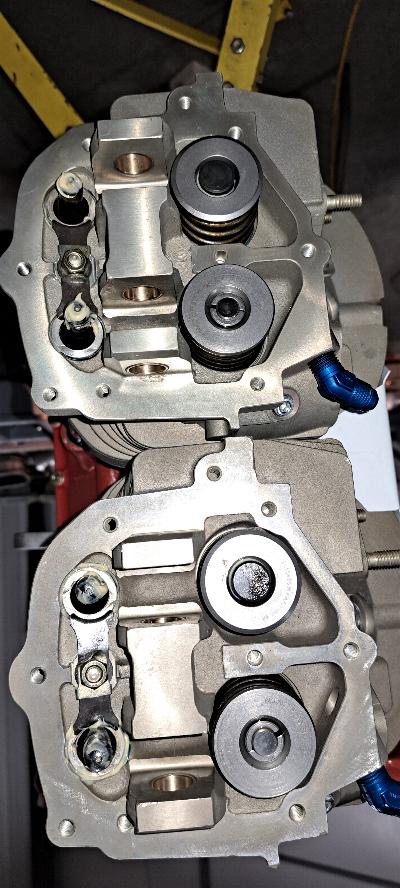
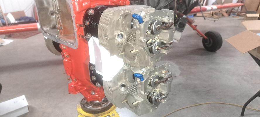
Nice, shiny, new cylinder heads ready for the pushrods and rockers.
This photo also shows the pushrod tube retainers in place.
Also note the cap on the exhaust valves. These are rotator
caps that are supposed to ensure that the valves rotate just a little
bit every time the rocker pushes the valve open. Most Lycoming
engines only have them on the exhaust valves. Some have none.
And the angle valve engines have them on both intake and exhaust.
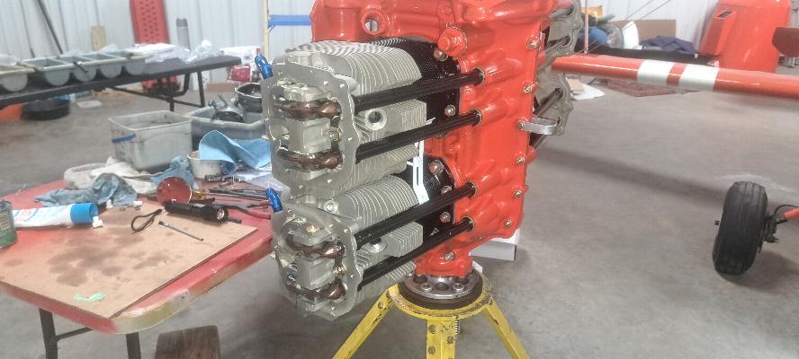
Rockers and pushrods installed. It's probalby worth noting that I
use an air gun to blow some assembly lube down onto the valve stems as
well. They would be fine without it, but I like to ensure
everything is coated just in case the engine ends up sitting for an
extended period of time before use. It happens a lot more often
then I would like to think. Had this been done when this engine
was originally overhauled, it wouldn't have been a rusted up bucket of
parts when the builder finally started flying the plane.
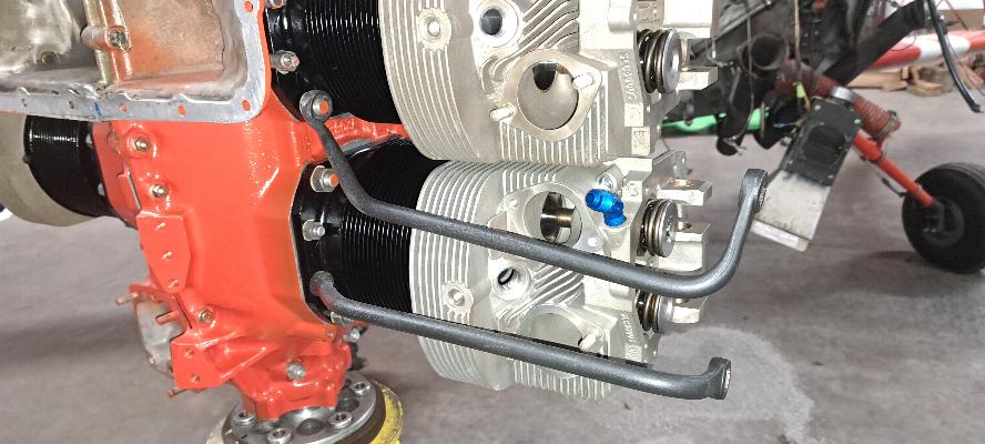
Drain tubes that drain the oil from the heads back to the sump installed.

Here's where things came to a screeching halt. Old oil pump gears
at the bottom of the photo and new gears above. The old gears
rode on a
shaft that is pinned into a two piece oil pump housing. The new
gears have the shaft as part of one gear. That doesn't work with
the old housing and I didn't order the new one piece housing.
I placed an order for it late today, but doubt it will ship before
Monday. So, I can't do anything more with the accessory case
until I get the rest of the oil pump; maybe on Wednesday. The old
gears were in good shape, but were being replaced for an old A.D that
dates back to the 1990s that had never been complied with.
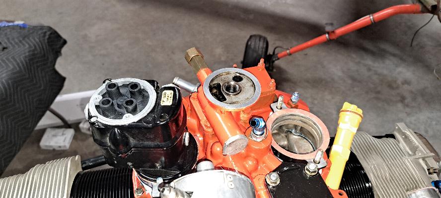
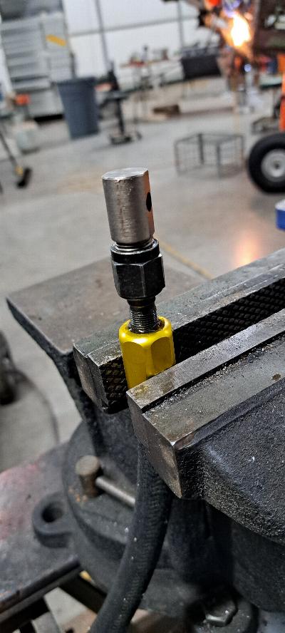
Next problem. I bought a set of used Slick magnetos from a RV
owner that was upgrading to Pmags. Both magnetos are impulse
coupled, which requires a spacer to be placed under the magneto to make
room for the impulse coupler. Since he was swapping to Pmags, he
even sent me the longer studs to accommodate the spacer.
Previously, only the left mag was coupled, so I needed the longer
studs and spacer for the new right magneto. I turned my old studs
out (the shorter stud in the photo above), then attempted to screw in
the longer stud. No go! He likely didn't know, but he had
oversized studs. They are a 5/16-18 thread, but are a few
thousandths larger to fit a worn out hole. Mine aren't worn, so
even after running a die over the threads several times, they are
still too big to fit into my 5/16-18 holes. I ordered new studs.
Of course these can be installed after the engine is assembled,
but will be a few days before I get them. So, Monday and Tuesday
of next week will be a time for cleaning and painting a few more parts,
and maybe get in some flying time in the other planes.
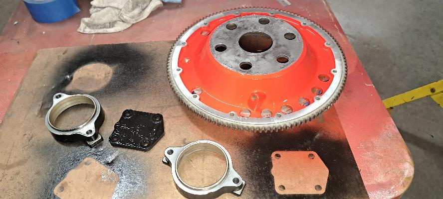
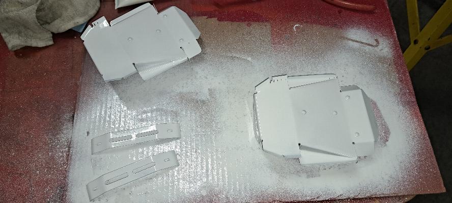
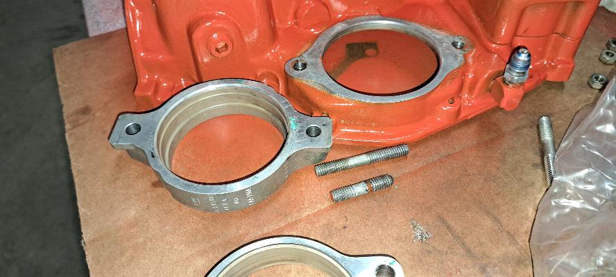
12/2/2024 - Not much to show today. I cleaned and painted
these parts. Two magneto spacers so I can install inpulse coupled
magnetos on both sides of the engine, a cover for the prop governor
accessory drive and the ring gear support. I found that the
gasket for the prop governor accessory drive cover was missing from the
overhaul kit as well as both magneto spacer gaskets and one magneto
gasket. I had spares on hand for all but the prop governor cover.
It was only $1.60 and free shipping, so not really worth trying
to battle my way through a warranty issue for the gasket set. For
some reason, they did include two sets of exhaust gaskets in the
overhaul kit. These are the expensive blow proof gaskets, so I
guess I came out OK on it anyway. I'll use them at some point in
time, although it's more likely that I'll just give them away when
someone is in need. The kit also included silicone valve cover
gaskets, but they are very thin as compared to the good ones that don't
leak. I was going to re-use the ones that were on the engine, but
found they were a bit deformed from decades of use and decided to try
the thin ones. I can always replace them if they leak.
I can't really move forward until I get the oil pump housing. I
am also waiting for the prop governor accessory drive cover gasket and
a pair of long magneto studs, but can install them anytime after the
engine is assembled. Hopefully the oil pump housing will arrive
shortly.

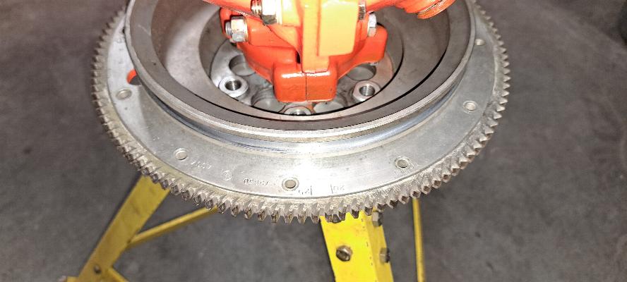
12/2/2024 - Quiet day while still waiting for parts. I lifted the engine off
the stand and installed the ring gear on the hub. I need the
timing marks on the ring gear to time the magnetos to the engine
after I install the accessory case. I also installed the new
valve covers. FedEx says the oil pump housing should arrive
tomorrow, so hopefully I can get the oil pump assembled and the
accessory housing on the engine tomorrow. I did repair a broken
brace inside the cowling you see standing on it's nose in the
background of this photo. A little bit of cutting, filing,
bending, drilling and riveting to repair the brace, but I failed to
take any photos.
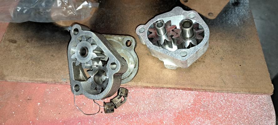
12/05/2024 - The oil pump housing was finally delivered. You can see
in this photo the new housing is one piece and the old one is two
pieces. The old housing has the pinion for the upper gear pinned into
the housing while the new housing has a simple hole machined and the
pinion shaft is part of the gear. At any rate, the parts are incompatible
with each other and there is an old A.D. against the old oil pump gear
set with one aluminum gear and one scintered gear. It had to be
changed.
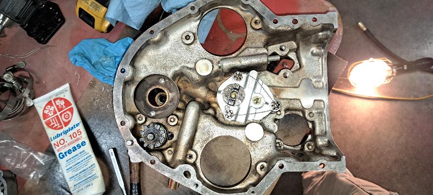
Oil pump mounted in the accessory case. Interestingly enough, the oil
splash shield mounted at the top of the case goes around the slinger on
the old camshaft. The new style camshaft has the gear as part of the
cam and the back side of the gear extends further back into the case.
This splash shield does not fit over the new gear, so I drilled the
two rivets out of the case and removed it. The newer cases have a
smaller splash shield that goes inside the cam gear. I have no way to
even acquire that splash shield short of buying another accessory case.
At worst the splash shield missing could potentially cause a leaky
tach drive. I'm already switching over to an electronic tach during
this update and am moving the mechanical tach to the front seat and
eliminating the old electronic tach that was in the front seat. If the
tach drive leaks, I'll switch back to the electronic tach for the front
seat and will put a sealed cap on the tach drive.
Looking
up into the accessory housing after it has been mounted. The
laminated
arm sticking down from the top of the photo is the fuel pump arm.
The big hole at the top of the picture is the oil suction tube
that is machined into the accessory case and oil tank.
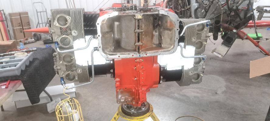
Intake manifolds and oil filler/dipstick mounted. It's also worth
noting that I found the oil drain tube from the rocker boxes was going
to chafe on the intercylinder baffles on both sides. So, I
installed a piece of tubing over the drain tube to pad it from the
(white) baffle.
Top
side. I am missing the long studs for mounting the impulse coupled
right side magneto. I bought a used set of mags for the plane and had
two impulse coupled mags. Not a problem. I just have to install
longer studs and a spacer to accommodate it. The mags came with the
longer studs, but they were oversized studs and don't fit my case as my
holes are still pristine. I ordered new studs today, so won't have
them until next week. I'll move on to other projects for a few days,
then will get back to mounting the magnetos, then will mount the engine
back onto the airframe after the studs arrive, probably early to mid
week next week.
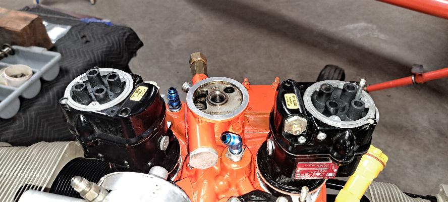
Left magneto sitting in place and and the spacer and gasket in
place
for the right mag. Normally, only the left mag has an impulse
coupler, so the spacer is not used on the right mag. However, the
used set I bought had an impulse on both mags, so I needed the spacer
for both mags to accommodate the impulse couplers. Also note that
the new studs are finally here and installed with the magneto spacer
mounted onto them.
The engine is set at 25° BTDC on the photo below, and the magneto
is inserted with the timing pin in place (timing pin is in the right
mag in this photo). In this case it is in the hole marked with an
"L" as both magnetors have a left hand rotation. Installing the
magneto in this manner has the mag at the firing point for #1 cylinder
and the engine set at the firing point for #1 cylinder. All
that's left to do is fine tune the timing with an inductive timing
tool. (magneto tweeter)
The 25° timing mark is lines up with the top seam in the case.
There are also marks on the front side of the ring gear that align
with a timing mark on the starter drive.
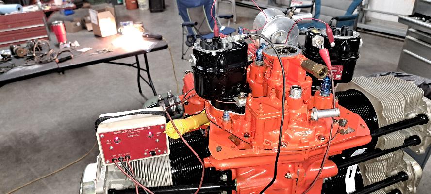
Magneto synchronizer hooked up to the magnetos. Since neither mag
is fastened down tight, in order to ensure a solid ground for timing
purposes, I have a ground jumper (the red wire) running between the
mags to ensure they are both grounded back to the synchronizer.
In this picture, you can see that both lights are on, indicating
the points are open. I have them synced perfectly together so
when I slowly rotate the engine, both lights come on together.
Note that the clamps are on the magneto bases now and they are
locked down in place.
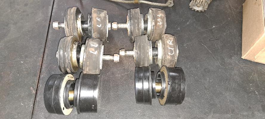
12/10/2024 - New engine mount bushings. The old ones look really
tired and have been in service for over 40 years. The old ones
are Lord mounts. The new ones are Barry mounts. I don't see
any difference. However, the Lord mounts are priced at $250 each,
and the Barry mounts were $156 each. That's a significant
difference for the same product.
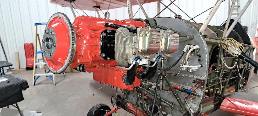
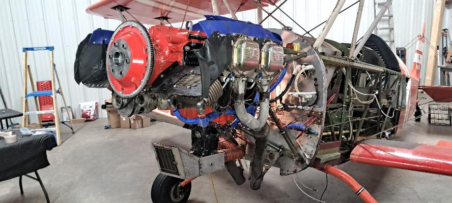
Ah, it's nice to see the engine mounted back onto the airframe. I
still have some assembly to do on the engine (carburetor, starter,
alternator and exhaust), then will start integrating the engine monitor
into the engine and airframe. Too bad the airframe is still
several months from flying. I didn't take another photo but did
get mount the primer lines and routed a few wires before I called it a
day.
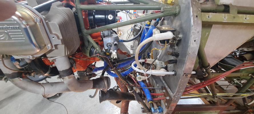
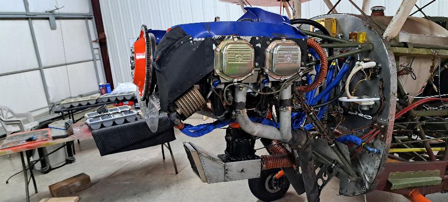
12/11/2024 - This photo doesn't look much different except in the
details. The headers are on the engine after being drilled
and exhaust Gas Temperature (EGT) thermocouples installed. Also
there are thermocouples screwed into the cylinder heads for Cylinder
Head Temperatures (CHT), a thermocouple screwed into the carburator for
Carb Throat Temperature (carb ice detection), and another screwed into
the oil filter
adapter for Oil temperature. There is one more for outside air
temp that will eventually be mounted to an external panel. On the
lower right of the photo, the red box is the fuel flow transducer, and
behind the engine are the Fuel, Oil, and Manifold Pressure transducers.
All of this will be integrated into three cables that go to an
intermediate box that will talk via a serial cable to the engine monitor
I am installing in the cockpit. The monitor will also be
connected to the magnetos to sense RPM. If you did your math,
this adds up to 16 gauges that are all monitored and displayed on that
one 3-1/8" instrument. Additionally, it also calculates fuel
usage based on fuel flow and percent power based on Manifold Pressure
and RPM. I have the same instrument installed in my RV-6 and
really like it.
12/12/2024 - Today was mostly about fabricating new hoses for the fuel
system. This is a photo of the mandrel in use driving the
inner
part of the fitting into the steel braid hose. Yes,
the hose is contains a steel braid and with neoprene on the
inside, another layer or neoprene outside of the steel braid, then a
cotton braided outer cover. It is very stiff, but flexible.
These hoses needed to be made up to do the additional routing of
the fuel system to include the fuel flow transducer.
All the hoses with blue firesleeve are new. Starting at the lower
corner of the photo, the hose runs from the fuel shutoff valve to the
electric fuel pump. Next to the electric fuel pump is the
gascolator (water separator and fuel screen). From the gascolator
there is an orange firesleeve hose that runs to the mechanical fuel
pump. The output of the mechanical fuel pump runs up to the red
block hiding behind the engine mount at the firewall that is the fuel flow transducer.
From the fuel flow transducer, the line runs down to the
carburetor fuel inlet underneath the engine.
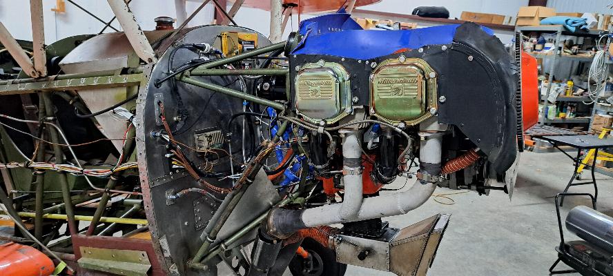
12/18/2024 - I've got the cooling baffling, spark plugs, and ignition
leads installed now as well as all the thermocouples, transducers and
wiring to feed the CGR-30R engine monitor. Also the carb and
airbox are now installed.
12/22/2024 - The engine is complete and ready for
the cowling, which is months away.
Why was this engine that had always been in Chandler AZ so rusty inside???
I spent some time digging through the logs to try to understand why
this engine had so much internal corrosion despite coming from a dry
climate. From the logs, here's the story with some speculation on my
part to fill in the blanks:
This engine was last overhauled in
January 1969. Here we are almost 56 years later tearing it down,
not because it leaks oil or runs poorly, but due to oil consumption and
a couple of cylinders just starting to get soft on compression. That's
actually pretty good service from an engine that was never started
until it was already a hot mess of corrosion and past calender TBO. The first engine run
following the 1969 overhaul was in 1981.
Apparently the owner purchased the overhauled engine for the Biplane project
he
was building, and it sat in his garage until it was ready to use.
Scratch building a large biplane is a daunting task and very time
consuming. It takes many years to bring that dream to fruition.
Now,
one would expect that since this was in Chandler, AZ, it would be
considered to be dry storage. However, even in AZ, there is
moisture,
and frost during the winter. I would guess it was in a cold
garage (or hangar) and
with the hot/cold cycles of the days and nights during the winter, it
was enough to produce some condensation in the engine.
Consequently,
there was some pitting on the crankshaft, rust on the camshaft, rust on
the cam tappets, and significant amounts of rust in the lower part of
the cylinder bores. The engine had definitely not been pickled,
nor
had it been properly assembled with assembly lube. Likely
they followed the manual and assembled the engine with engine oil.
That
works great if the engine is going to be put in service right away. But
if
it is going to sit, it needs a thorough coating of assembly lube on
everything steel, and or it must be pickled using a tacky fogging oil
before storage; or both! To it's credit, despite significant corrosion
on the
tappets, camshaft and cylinder bores, the engine had run 350 hours and
was still
running strong. The top of the intake lobes were starting to
deteriorate, but it would take another few hundred hours for that to
make a significant impact to the performance of the engine. I
mainly
tore into the engine due to the higher than normal oil consumption and
waning compression on one or two cylinders.
The oil consumption was likely due to the pitting in the
cylinders and the compression issues were due to corrosion on the valve
seats from before it was ever started. I installed new Superior cylinders, but the old ones
have since been honed to clean them up, valves and seats ground and are
in serviceable condition meeting specs. -Jeff