Lycoming IO-360-A1B6D overhaul due to cracked case.
This engine came from a Cessna Cardinal RG belonging to a friend.
I've flown this plane in the past. Nice plane and good
engine that had a little bit of a vibration in it. That was
compensated with a dynamic balance of the prop, but those stresses take
their toll. I can't say that was the cause, but the engine
started leaking oil through a stud on #1 cylinder. A shop in
Oregon investigated the oil leak for him and found the case was cracked
through the left lower stud. My friend removed the engine and
brought it to me. The engine is over 1000 hrs since overhaul and
has a pretty significant oil consumption even before it started leaking
oil. My recommendation was that as long as we have to pull
everything out of the case anyway, and it is clearly due for some
cylinder work, let's go ahead and complete a major overhaul. In
that event, it is unlikely he will ever have to deal with anything major
on the engine again. We'll make decisions on where to send things
depending on what we see and how things measure when we tear it down.
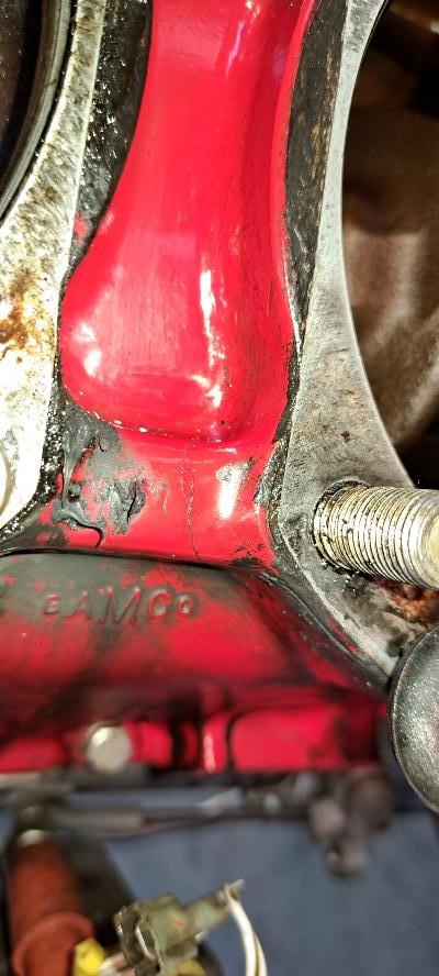
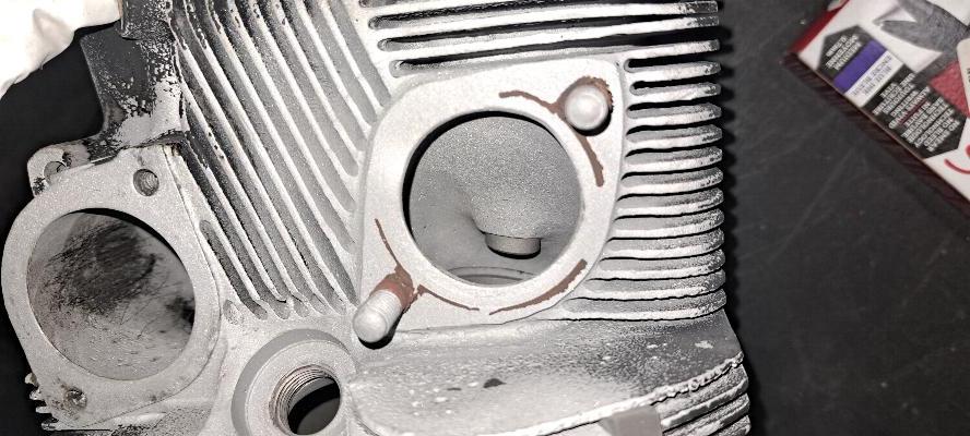
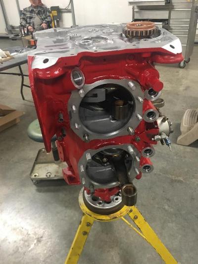
11/18/2024 - Here's why it's in my shop. This is the engine case
just behind #1 cylinder. Note the crack coming through the case
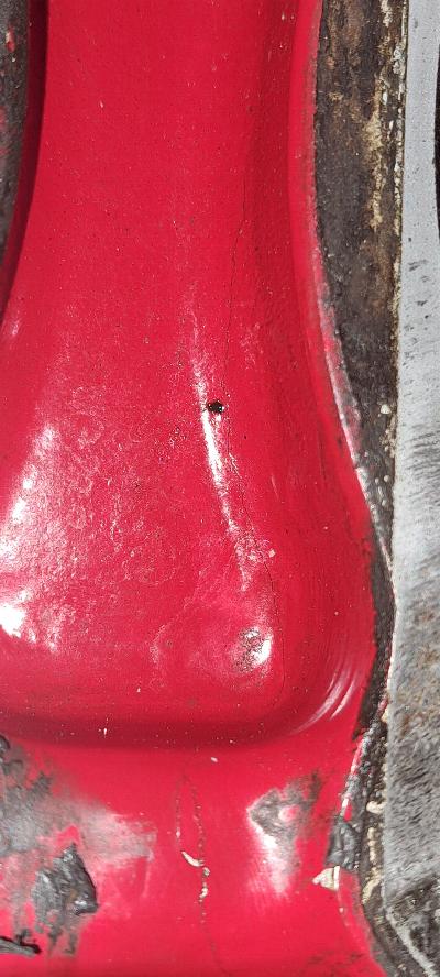
just behind cylinder base stud. A closer examination below shows that
crack runs up the casting along behind the cylinder. This case
wasn't far from total failure. I don't think this is one DIVCO would fix.
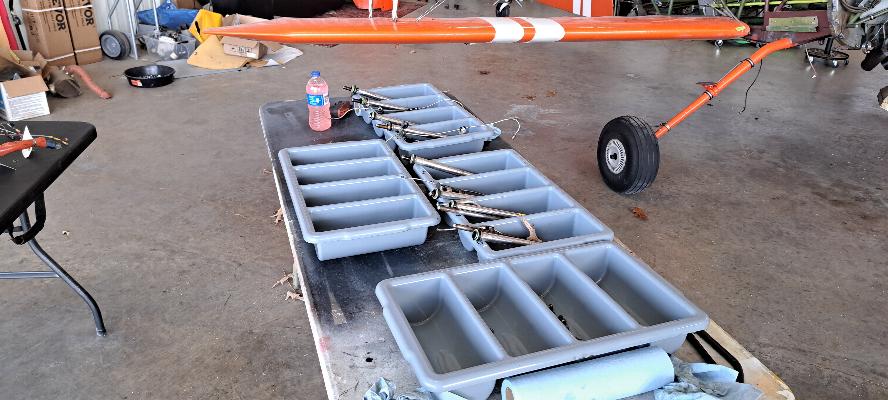
Sorting trays all laid out to keep things organized.

It arrived with Cyl #1 already off.

I put Will Pendergrass to work tearing down the engine with some assistance and supervision on my part.

He's about got it. Not much more to do but split the case and
start measuring parts. Oh, and a few days of degreasing and bead
blasting parts.

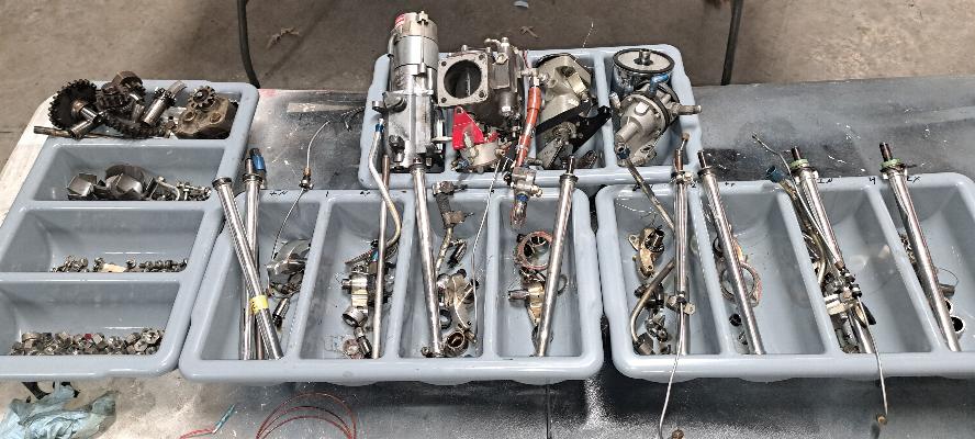
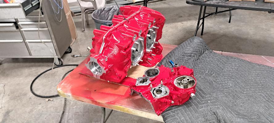
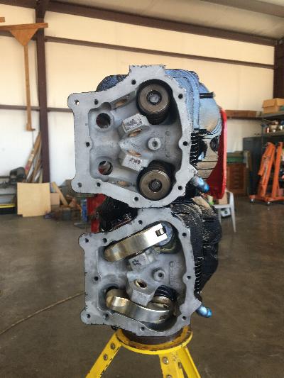
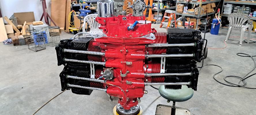
End of the day, here's the engine stacked on 3 tables. Those big
ears on the side of the crankshaft are floating counterweights to help
smooth out the engine.
The news on the internals was a mixed bag; mostly good. The cam
and cam followers are in good used condition and will be sent to a
machine shop for regrind and hardening. The crankshaft is in good
condition, but the main journals are at minimum for new spec and the
rod journals are worn a bit beyond minimums. So, the crank will
have to go to a shop for regrinding. We will also have the crank
rebalanced. The connecting rods are going to Santa Fe to be
checked for measurements and balancing along with the wrist pins and
cylinders for honing and valve work. The cylinders appear to be
in good condition, but were not new when installed, so this is the
second run on them. We'll have to see how they measure. The
exhaust valves will likely show enough wear that it will be time to
replace them and the cylinders will need exhaust valve guides for sure.
One interesting thing I found. I don't know if someone had
attempted to replace the front seal on the engine or it had been
assembled this way, but they had used the split front seal rather than the stretched seal. That is actually an
acceptable way to install it if you have to. But, they had also
failed to install the garter spring, which is the spring that goes
inside the seal from the back to create some pressure to hold the lips
of the seal on the crankshaft. It also serves to align the seal
halves when the seal is split like this one was. Never-the-less, it
wasn't leaking a lot of oil from it. It is truly rare for me to
tear down an engine and not find something wonky inside it from the
original build.
11/19/2024 - I didn't write an update today. I simply forgot to take any pictures.
We spent all day cleaning parts and bead blasting the lead deposits out
of the cylinders. The crank, cam, and cam followers are all packaged
up and ready for Larry (the owner) to drop off at Aircraft Specialties
for machine work. The cylinders, connecting rods, and wrist pins are
all packaged up and ready to go to Santa Fe for honing, valve guides, and
valve and seat grinding, and balancing of connecting rods.
11/20/2024 - All the case parts, bolts and nuts in the left tray.
The accessories in the back tray. And all the parts for the
cylinders in the front trays. This stuff goes on the shelf while
the rest of the engine is making its way through various machine shops.
When I start building the engine, this stuff comes back out for
cleaning before installation. Note the rocker arms laying in the
trays. Yes, those are roller rockers, so roll on needle bearings
on the shafts rather than bushings and have a roller over the end of
the valve to avoid side loading the valves when they open. I
found 3 of the rotator caps that sit on top of the valves were not
rotating, so the roller rockers had worn grooves into the caps.
They will need to be replaced. I'll try to get a photo of
that before it goes back together. Also note the pushrod tube on
the far right. That's #4 exhaust pushrod. The cylinder base
nut next to it was overtorqued and I banged into the tube denting it
when the base nut popped loose. I was able to force a 5/8" dowel
rod down through the tube to push the dent out of it so the push rod
won't drag and wear a hole through the tube from the inside.

Cylinder after bead blasting.
The exhaust and intake ports after bead blasting all the lead salts out of the ports.

Inside of the cylinder heads after bead blasting.
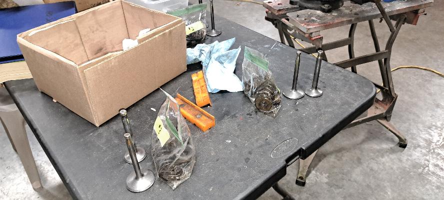
Valves following bead blasting and cleaning with a wire wheel.
Each baggy has the valve keepers, springs, retainers and valves.
11/22/2024 - No pictures to post. We searched the local hardware
stores for the "right" shade or red paint to match the red Cardinal the
engine came off. No luck so far, so may have to go to the local
auto paint store and have them match it. The owner went to a
local paint shop and had them do a color match. Theymixed some
matching paint and put it in spray cans for him to use, then sold him
some Y2K PolyUrethane Clear Coat. It does look nice, but I'm not
enthusiastic about spraying polyurethanes in the hangar, and especially
without a respirator. Since it was a nice day, he did the paint
work outside. Yes, I have respirators, but he opted not to use
one outside.
The internal parts from this engine will be going to Aircraft
Specialties for overhaul. My gripe with Aircraft Specialties is
that they will almost always grind down a perfectly good crankshaft,
whether it needs it or not. That pads the bill for their machine
shop services, but they may also do that for liability protection.
I haven't had any problems with their finished work. When I
measured the crank on this engine, the mains measured just outside of
new limits and the rod journals measured .0015" under the limits.
Since it needs to be reground, the crank will go to Aircraft
Specialties for regrinding and balance. The camshaft and cam
followers are in good condition, so will also go to Aircraft
Specialties for overhaul.

Overhaul process for aircraft crankshafts:
Regrinding an aircraft crankshaft is significantly different from
regrinding an automotive crank. These cranks are nitrided, so are
very hard. That doesn't make a big difference to grinding, but
does affect the process as they need to go through a Nitriding process.
When the machine shop gets the crankshaft, they always dimension the
crankshafts. They measure each bearing surface in at least
two directions to check for wear. Then measure the crank
flange for runout (or wobble). The measure the center main
bearing
for runout (straightness of the crankshaft). If the crankshaft
meets minimium specs to be reground, they grind each journal to spec.
On a Lycoming, they can be ground .003, .006, .009, .010, .012, and
.015 undersized. Continental uses .010 and .020 undersize
bearings, then it's time to retire the crankshaft. The rod
journals will always be ground to the
same undersize and the main journals will always be ground to the same
undersize. But, the rods and mains may be ground to different
undersize depending on the condition of the crankshaft. I had one
recently that came back with the Mains ground .006" undersize and the
rods ground .003" undersize. One thing that is different about an
aircraft crankshaft is that there are not cut edges on a journal.
Every crankshaft I have seen has a minimum radius of 3/32 of an
inch at the edges of every journal. A sharp edge is a stress
riser and will cause the crank to fail. I've seen one aircraft
crankshaft an owner re-installed that had one rod journal that was cut
with a sharp edge. The crankshaft broke at that journal with the
crack starting at that sharp edge causing an emergency forced landing
in with the plane and proving to be very costly to the owner as the
plane was grounded 800 miles from home while an unknown shop
overhauled his engine. The shop may balance the
crankshaft at this point, but that is optional and very few crankshafts
get properly balanced. I almost always pay to have the
crankshaft balanced. Most people do not. But I love a
smooth engine. It is surprising how much they grind off a crank
to
balance them properly even though it may not necessarily have been a
rough running engine. Once balanced, the crankshaft waits for the
shop to do a weekend furnace run. The shop puts a batch of
crankshafts into a furnace where they are heated in an agitated ammonia or nitrogen atmosphere to a
temperature between 450 and 600°C. The
furnace temperature is ramped up slowly, then held at temperature for
an extended
period of time. The nitrogen reacts with the alloying elements
of the steel at the surface of the
crankshaft creating the nitrided surface that runs roughly .030" deep
into the metal. The nitrided surface is very hard and resistant
to wear and fatigue. Following the furnace run, the crankshaft
goes back to
the machine shop for pollishing. The crank is cleaned once again
and the crank journals are polished with an abrasive belt while turning
in a lathe. Once polished they are measured again for dimensions.
The crank has one last stop to make over in the plating shop.
In the plating shop, just the front of the crankshaft (flange and
front seal surface) are dipped into a vat for electro-plating with
cadmium for corrosion resistance. Once plated, the crankshaft is
ready to be shipped back for return service. You can see the
previous
cad plating on this crannkshaft in the photo above. This
crankshaft has been overhauled once before and was run a second time
with the journals polished at standard size. Now they are showing
some wear and will have to be reground to under size.
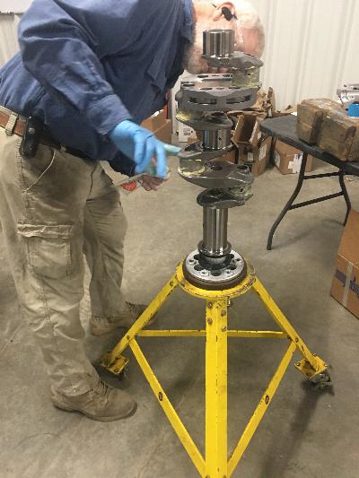
It's worth noting that this crankshaft has "free floating"
counterweights between #3 and #4 rod journals. The counterweights
are on pins and actually move around on those pins. The weights
are there to smooth the engine. If you think about it, this is a
4 cylinder engine with the same displacement as a truck engine. I
am aways amazed that they can make their horsepower as smoothly as they
do. During the overhaul process, the counterweighs are removed
and cleaned. The mounting pins may be replaced. There is
also a dowel pin at the back of the crank that is used to index the
gear that drives the accessories. That dowel pin is always
removed and replaced.

11/25/2024 - The new engine case sitting next to the old case. We
still need to move some plugs, fittings and oilers between the cases.
But gosh, isn't that new case pretty?
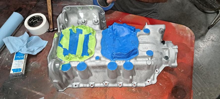
Masking off the new case half getting ready for paint. It should
probably be noted that any surface where a bolt seats that requires a
critical torque must be paint free. Specifically, that is where
the cylinder and case studs and throughbolts are torqued down.
Additionally, any surface you expect to seal also needs to be
paint free. That is why you see a bolt and washer covering the
holes where the bolts seat in the front collar of the case as well as
masking over the pushrod tube seats and cylinder seating area.

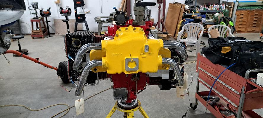
Painted Cardinal red to match the plane where it will be mounted.
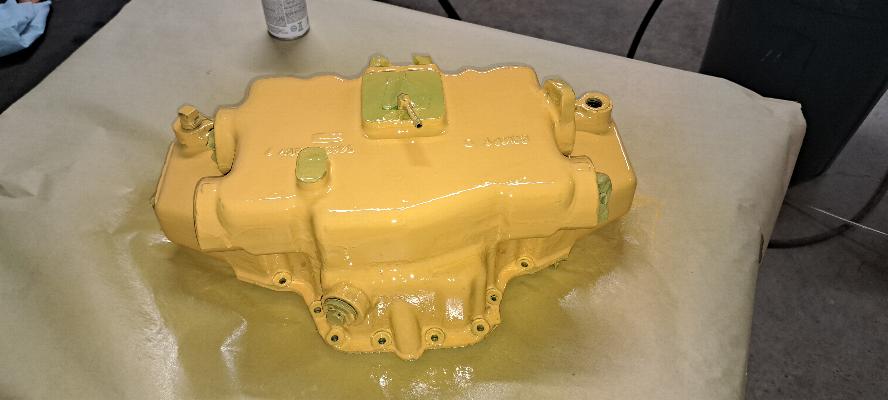
I asked, "Why the yellow sump?" Well, 'cause it was already yellow and was easier to repaint the same color.

Masking removed. Bolts and washers were still in the front collar holes.
Case halves zip tied together for storage and the masking removed from
the case halves and accessory case. It is pretty! Now it
goes on the shelf for several weeks until we get the crank, cam, cam
followers, connecting rods, wrist pins, and cylinders back. We'll
also be ordering new pistons, rings, bearings, and all the other
associated overhaul parts once we know how far undersize the crank gets
ground.
12/3/2024 - Crank, cam and cam followers were delivered to
Aircraft Specialties today. They estimated 6 - 8 week turnaround.
If so, we'll be building this engine in February.
1/15/2025 - Parts are starting to arrive for this engine. The
crank was turned down M003, .003" undersize on both mains and rod pins.
The crank and cam followers (tappets/lifter bodies) should be
shipped this week, but I don't have them yet. The cam failed to
make spec, so a new camshaft was purchased. The valves and valve
guides all meet spec, so the valves and seats were ground and cylinders
honed. All the overhaul parts should be arriving with FedEx this
morning. I'm finishing the center section tank for the Biplane, then will get started building this engine probably the last week of January or the first week of February.

2/1/2025 - The crankshaft is here and it is a piece of art! The
first thing I do to is is take some emory cloth and scuff a helix into
the cad plated surface just behind the prop flange. The front
seal doesn't necessarily seal very well on the cad plated surface, but
scuffing a helix into it so when the engine is running the helix draws
any oil wanting to weep through the seal gets drawn back into the
engine. This trick is from a Continental service bulletin, but I
find it works quite well on both Continental and Lycoming engines.

The first order of business was to inspect the new case. I called
a halt to the build first thing as until I got more clarification.
Notice any difference between the new case above and the old case
below?

The old case has an "O" ring around every stud and through bolt that
goes through the case. Look at the upper photo of the new case
again. The center and front "through bolts" have no relief cut for
an O-ring. First I checked the parts manual. My parts
manual only calls for the small set of O-rings at the front of the case
and the larger set of O-rings around the back studs at the back main
bearing. The other two aren't shown, but it's a lousy drawing
that doesn't show the inside of the right half of the case, so is less
than clear. So, I called a friend that had recently overhauled
the exact same model engine. He sent me photos of his, which also
has a relief cut for O-rings at every stud. Is this a machining
error? Or is it a revision? I know Continental does not use
an O-ring in this position, but I've also seen a lot of case leaks on
Continentals at the through bolts. This is the beauty of having
another mechanic here on the field that has also done a lot of
overhauls. We discussed it and agreed that this is a newer
revision of the engine case and Lycoming must have decided those
O-rings were unnecessary. It doesn't make me feel warm and fuzzy,
so I'll use a bit of Hylomar and silk thread around the 4 through bolts
to ensure as best I can that they don't leak. OK, this mystery is resolved to
the best of my ability for a Saturday. On to assembling the
engine!
Later when I
installed the through bolts, I found they were an interference fit, so
the likelihood of them leaking is significantly reduced. The
through bolts were not an interfenence fit when I removed them from the
old case. If they were at one time, they weren't anymore as they
came right out with a gentle tap.
Time to get started with the assembly of this engine. At this
point in time, I have the front seal already mounted on the engine.
That front seal is not a split seal. I remove the spring
from the lip of the seal and put it back together on the
crankshaft. I boil the seal in water in the microwave, then
stretch it over the prop flange while it is warm using a selection of
tire spoons to avoid scratching the crank flange. Once it is over
the flange, it
quickly shrinks back to shape and I insert the spring into the
back of the seal. It is always a struggle to get these on, but it
always works. It took three attempts to install this seal before
I could get the leverage to stretch it over the flange. We did a
video of installing the seal, but the struggle is real and the language
may not have been appropriate for broadcasting.
At this point in time I am putting Lubriplate (TM) Assembly lube on the rod journals in preparation to install the rod bearings.

Rods are installed on the crankshaft, but the rod bolts are not
torqued. Rod bolts and nuts are always replaced on overhaul.

A torque spec on these rod bolts does not exist. You tighten
them down until the bolt stretches to meet the length specified in the
overhaul manual. In this picture, I'm using my 2 - 3" Micrometer
to measure the rod bolt length. I torqued them to 30 ft lb, then
stepped them up at 5 ft lb increments until I got the proper stretch.
In the case of this engine, that worked out to
be at exactly 50 ft. lb. on my 1/2" torque wrench to make the minimum
stretch. I had written in my manual from a previous overhaul that
it was 53 ft.lb., which would have still been within the stretch spec
for this engine.
Inserting the front bearing that takes the prop loads. This
bearing is split at the top and bottom in this picture,
or at the 90° and 270° positions when the case is sitting in
the
plane. The bearing has to be installed onto the crankshaft,
then the crankshaft carefully placed into the case while aligning the
front bearing onto the alignment dowels by feel as you can't see them
under the crankshaft. It is really easy to put them in and miss
the alignment dowels (yes, I did that on my own engine!) In order
to ensure that the bearing is
fully seated on the alignment dowels, in this photo I have the bearing
in place and am marking the sides of the bearing with a pen along the
edge of the case. When I install the crankshaft with the bearing
on it, if the lines drawn on the bearing are not fully seated to the
edge of the case, then
the bearing is not properly seated onto the dowels. If you
tighten down the case with the bearing not properly seated, you have
just damaged a very expensive bearing.
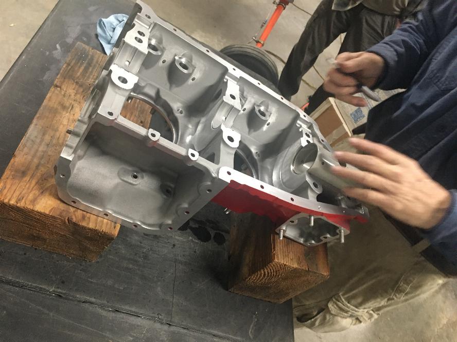
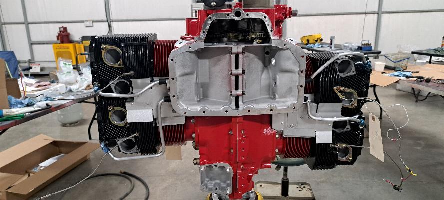
Notice the large flat area in the case just aft of the front bearing in the photo above.
That is the thrust bearing surface for this engine. Yes,
Lycoming has a machined face in front of the #1 rod throw that rides
against a machined aluminum surface in the case. That's what you
are pulling against all the time when flying behind your Lycoming
engine. That's not a critisizm as it clearly works. This
isn't a machined surface that getsfilled in and recut when a case or
crankshaft is overhauled as that would leave an unacceptable amount of
end play in the crankshaft, and there are a lot of Lycoming engines out
there with 6000 or even 8000 hours on the case that have been through
multiple overhauls.
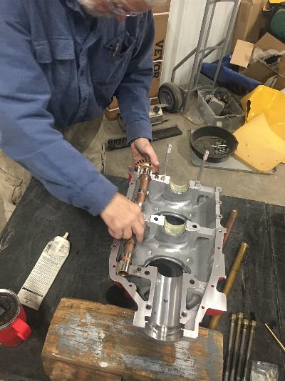
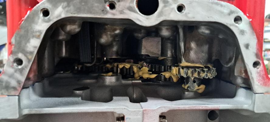
Setting the camshaft into the right side of the case after lubricating
the camshaft bearing surfaces with assembly lube. The cam
followers are already installed under the camshaft with the faces of
the tappets lubricated with Moly/Zinc Cam break-in grease. Note
the big hole in the middle of the front saddle where the front bearing
sits. This is the oil transfer port where the prop governor
transfers oil through the front bearing into the center bore of the
crankshaft to control the prop pitch with oil pressure from the
governor. The black stuff on the face of the cam followers below
is the moly/zinc break-in grease. Each cam lobe was also coated
with this grease before the case halves were mated together.

The crankshaft is installed into the left half of the case with the
front bearing seated onto the alignment dowels. The large hole
beetween the two halves of the bearing shells aligns with the oil
transfer port in the right case half. In this photo, you
can see the oil transfer port also aligned on the crankshaft. The
bearing supports the crankshaft at the front and back of the bearing
face, and has an area between the two supports for the oil transfer
port. So, the crankshaft is completely surrounded with
pressurized oil inside
the bearing shell so oil transfers to the prop all the time, not just
when the port aligns with the hole in the bearing. The prop
governor is regulating the pressure at that hole in the front bearing
and can run as high as 410 psi. That is why the oil transfer line
and fittings from the governor to the prop hub are required to be steel
or stainless steel.

Painting the left side of the case with Hylomar Blue sealer. That little bottle of sealer is about $100.

Laying silk thread into the sealing surface of the left half of the
case. You can see in the background that I have both surfaces
painted with a thin coat of Hylomar. The manual only calls for
coating one surface, but I find that I get no leaks with this method.

I'm putting a bit of silicone sealant on the outer flange of the front
seal, then will push the seal into place. This is the only place
silicone sealant should ever be used in an aircraft engine.

The left half of the case has been mated to the right half of the case.
Note the little pieces of safety wire tied around a couple of
cylinder base studs. That is some .020" safety wire that is
wrapped around the camshaft to hold it into the right case half while
lowering the right half down onto the left half. With the cam
trapped into it's bearing blocks, it also holds the cam followers captive
into the right half of the case. You can gently lower the right
half of the case onto the left half without having all the parts
falling out. Once in place, you snip the safety wire and pull it
out.
Also note above that the through bolts are not installed yet.
That's why there are two studs missing at the front of #1 and #3
cylinders on the case.
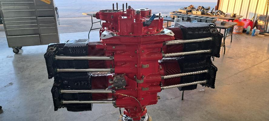
The engine goes onto the stand for further assembly. Note that
the through bolts are in the case at this point in time. We
polished the heck out of the bolts and still found them to be a quite
snug interference fit. They had to be driven in with brass drift
and 2# hammer. It would be kinder for the through bolts if I did this with a lead hammer... if I owned one.

Fuel divider and a few other goodies getting installed onto the case.
Oil temp thermocouple is screwed into the front of this case.

The case bolts are all torqued in and the 3 internal bolts safety wired.

And that pesky castilated case nut that's hidden under the cam gear.
Lots of people tell me about building a special wrench to get to
that nut. You can actually get to it with a tool common to every
aircraft mechanic's tool set. The 9/16" cylinder base wrench will
do it. That little bit of scoring under the nut was my action
with a punch trying to get at the cotter key to bend the tangs on it
properly.

The cylinders are all painted and ready for installation on Monday.
That's going to smell funny on the first run of this engine!
2/5/2025 - Installed all the cylinders. This particular engine
has roller rocker arms installed on it. I've never seen them in a
Lycoming engine before, so have to look for an adverse effects or wear
caused by them. The back two cylinders don't have the rockers installed. The explanation is below.
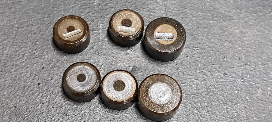
And there it is. The valve rotator caps rather than rotating as
they should under a standard rocker arm, have a groove worn into them
from the roller on the rocker arm. I had spotted the top three previously
and had new caps ordered to replace them. But upon closer
inspection this morning, I found three more than were showing a small
amount of wear that was only visible when light was reflected against
the top surface. I put the assembly on hold and ordered more
replacement rotator caps. They should be here on Thursday.
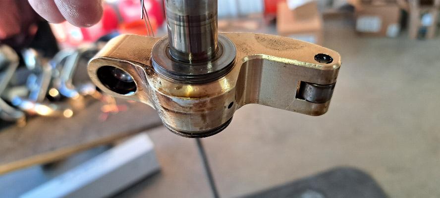
This is the roller rocker arm used in this engine. While it
caused some wear issues with the valve rotator caps, the concept of
roller rockers clearly works. This engine had 1000 hours since it
was last overhauled. The valves and valve guides, including the
exhaust guides, still met new spec and did not require replacement.
I have never seen a Lycoming or Continental engine that didn't
need new exhaust valve guides by 1000 hours. This one did not.
These are kind of a bugger to install with needle bearings and
thrust bushing both inside and on the side of the rocker arms.

While waiting for the valve components to arrive, I decided to assemble
the gear train in the accessory case instead. This was a test
assembly, then the gears were removed and cleaned, then reassembled and
packed with assembly lube before installing the accessory case.
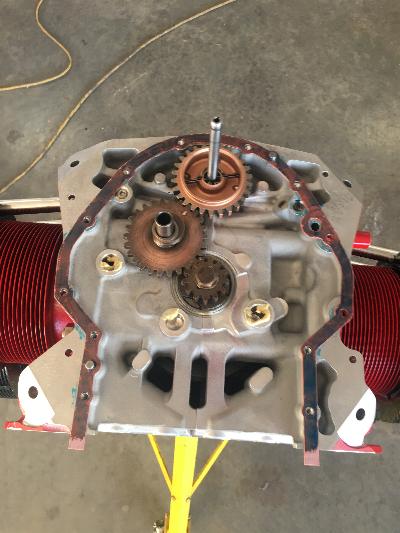
In order from the top to bottom, the gears are Camshaft, Cam
idler gear, to the left is the magneto drive gear/coupling, and below
that is the idler gear that drives the prop governor. The gear
that is laying on it's side is the vacuum pump drive gear. The
oil pump drive and prop governor drive are missing as they are
installed in the accessory case. The vacuum pump gear will also
be installed in the accessory case before the accessory case gets
installed onto the engine. The long shaft that is sticking out of
the cam gear below is the tachometer drive shaft. It sticks out
through the accessory case through a bushing and seal where the
tach cable gets plugged into the end of the tach drive shaft and
screwed onto the tach drive on the back of the accessory case.
This engine was part of Lycomings "76" series engines, designed
to be simpler and less expensive than the previous engines. They
were neither. However, they used a single drive dual magneto,
which turned out to be a terrible idea and created a single point of
failure for the ignition systems. They are reliable, but have now
been disowned and new production ceased by Bendix, the owner of this
magneto design. Now you can only get them repaired, but not
replaced. We considered changing this engine to the more standard
dual magneto setup during overhaul, especially since we were replacing
the engine case. But the cost of a different accessory case and
all the internal drive gears was prohibitively high.
Gears in place, on the back of the engine. The gear seating
lubricated for gears in the accessory case to seat into. The
gasket is in place and painted with Hylomar. Below, the oil pump
is assembled, packed with assembly lube and bolted into the accesory
case. The vacuum pump drive gear is installed at the top and the
prop governor drive gear is installed at the bottom. The fuel
pump push rod is in place in the sleeve in the center or the accessory
case. It rides on the eccentric cam that is built into the
camshaft idler gear above.

Accessory case is installed with the gears well lubricated with assembly lube. This is a look up inside from the bottom.
Accessory case installed and torqued down.

This is the ball and spring that goes inside the oil pressure
regulator. In this model, you remove the regulator and add a
washer behind the spring to increase the default oil pressure.
There is another model avilable that you can just turn an
adjustment bolt in to tighten the spring and raise the oil pressure.
The two models are interchangeable.
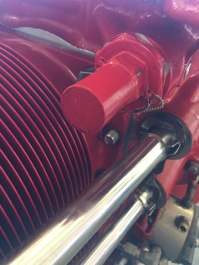
The oil pressure regulator screws into the case just behind #3 cylinder, then gets safetied into place.

Oil filter canister, fuel pump and
prop governor installed.

2/7/2025 - After a week of FedEx Ground losing parts and shipping them
to the wrong end of the country, Air Power overnighted us the
replacement parts. Yes those three little rotator caps from a few pictures up have held us at a standstill all week. This
afternoon we could finally get back to work. Now the cylinders are
mounted and the intercylinder cooling baffles are installed.
A word about Air Power for parts. Their prices are lowest I can
find. There is no tax on the parts. And Fed Ex Ground
shipping is free. Overall, I save about 25% by buying my
Luycoming (Superior) and Continental parts through them. The
fiasco this week was not their fault, but the ineptitude at FedEx
ground. Air Power overnighted me a second set of parts at no
charge and will settle up with me once FedEx actually finds and
delivers the parts that were supposed to be here two days ago, then
they will have them shipped back to them. Now that is service,
and I am very pleased with them.
Intercylinder baffles shown from below. These force air around
the bottom of the cylinders and cylinder heads to help them cool.
Also, the oil drains for the cylinder heads are now installed.

The fuel injectors are installed into the heads and fuel injection
lines are on, with my disassembly labels still hanging on them I
still need to put all the adel clamps onto the injector lines to
support them.
Oil tank and intake runners are now installed.

Fuel injector line supports are in place now. There are still a
few more things to go back onto this, but I hope to complete this
engine tomorrow and get it loaded into the shipping crate to head back
home.

2/8/2025 - Fuel servo and all the plumbing installed. The engine is complete and time to clean up the shop.
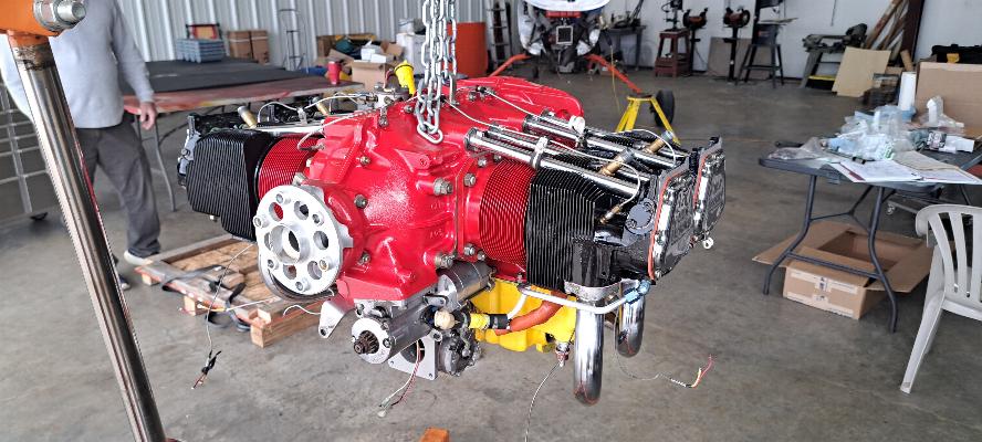
Engine is on the hoist and headed into it's crate for the trip back to Oregon. Bye, bye...
