2024 - 2025 Electrical/Instrumentation Modifications
Engine overhaul
Electronics/Electrical
Fuel System
Trim System
Fabric Recover
Item #6 from the Rebuild page:
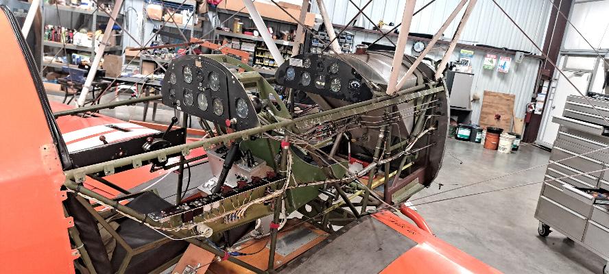
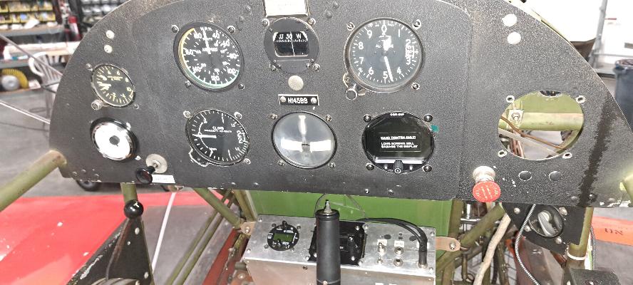
The rear cockpit is a hodge-podge of instruments and radios
mounted whereever they could be fitted with little regard to ergonomics
or visual scan. I don't know that I'll straighten it all out, but
I have purchased and Electronics International CGR-30 to consolidate
all the engine instrumentation.
11/13/2024 - Well now she's looking kind of naked. All the sides,
top deck and belly skins are removed. They will all need to be
cleaned and repainted, but having them off will also give me much
better access to the instrument panel, plumbing, and wiring as I change
much of it.
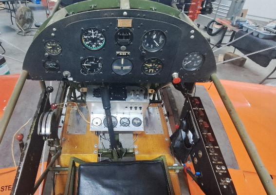
12/7/2027 - Pearl Harbor Day - While I wait for a few minor parts for
the engine, I started cleaning up the rear cockpit. The first
thing was to remove the instruments that will be replaced by the new
engine monitor. Several old instruments will come out of the
panel, and the bottom subpanel that's between my knees will go away all
together. I'll still need the forward part of the subpanel for
the radio and transponder, but the rest is being removed.
Lots of other changes as well. The control stick heads will be
replaced with new handles that will include integrated trim and PTT
buttons. The elevator trim control (the Red knob) at the lower
left of the photo will be removed. I may rearrange the switch
panel on the right side as it is a bulky and inefficient layout.
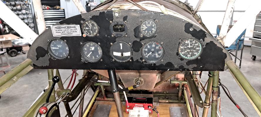
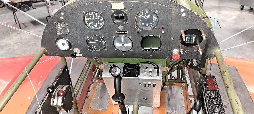
This is the front cockpit. There aren't going to be any major
changes here. The electronic tachometer at the right side of the
panel is inaccurate, so the old mechanical tach from the rear seat will
be moving to the front cockpit to replace it. The engine monitor
going in the rear panel will have the tachometer integrated as part of
the monitor. The pipes and hoses running along the right side of
the cockpit are being removed as they are there for Mechanical Oil
Pressure, Fuel Pressure and Manifold Pressure gauges. Those will
be replaced by electronic transducers mounted at the firewall and are
integraded as part of the engine monitor. The same is true for the
wiring from the CHT and EGT gauges as they will also be integrated as a
part of the engine monitor.

12/9/2024 - Here's all the stuff that came out of the rear cockpit so
far. The subpanel from between my knees is on the left.
Combination Oil Temp, Oil Pressure, Fuel Pressure gauge,
Tachometer, Manifold pressure, Ammeter, Exhaust Gas Temperature, and
dual Cylinder Heat Temperature gauges. All of these work and have
the thermocouples and all but the tach are up for grabs if you need
something. The electronic tach from the front cockpit will also
be up for grabs.
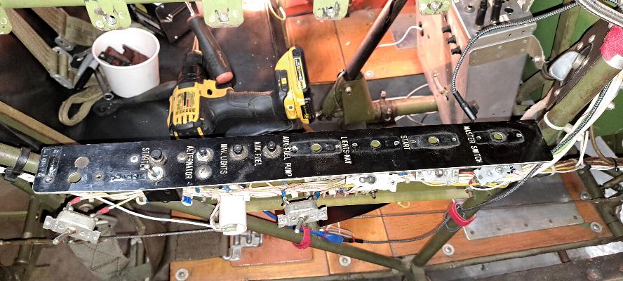
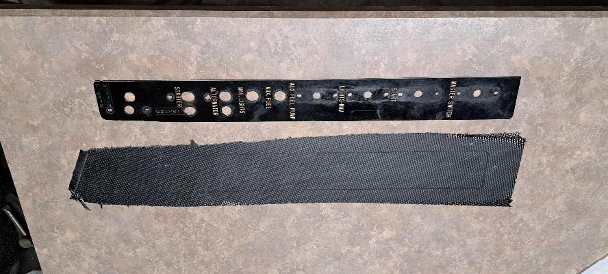
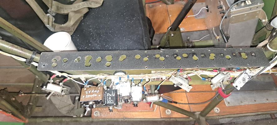
12/11/2024 - Building a new switch panel. This one was kind of
neat with military type covers over the switches. But the switch
covers are largely unnecessary and the switches are so spread out down
this panel that it takes too much room. I don't like reaching
back behind my elbow to reach switches. I'll build a new cover
for the panel and remount the switches in a much more compact design.
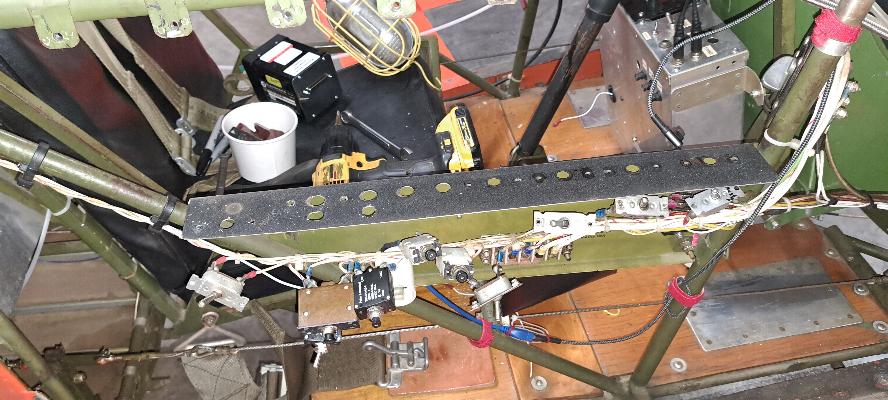
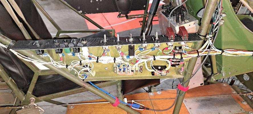
The panel that was under the plastic panel. All the switches and
breakers are still hooked up; just hanging below the panel. I'll
rearrange the wiring and switches when I get started mounting
everything into the new panel.
I'm going to fabricate a new cover from carbon fiber. This is a
simple wet layup of two pieces of carbon fiber on a waxed countertop
that I use for wet layups.
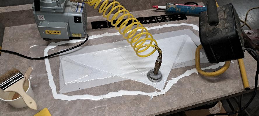
The layup is covered with peel ply (dacron fabric), then some felt to
absorb the excess resin, then vacuum bagged using a medical vacuum pump
and cheap painters masking plastic stuck to the board with the cheapest
caulking I could buy. It's cold in the hangar (roughly 55°
F), so that's my oil filled mini-heater set to blow onto the layup
overnight. It is set on low heat and is also thermostatically
controlled. Additionally, the warm exhaust from the cooling fan
on the vacuum pump is also blowing across the layup. Even using
West System Epoxy with the medium temp hardener for the layup and a bit
of heat, it will probably still take at least a couple of days to cure.
Before someone tells me I'm not supposed to do layups this cold,
it should be noted that this is NOT a structural layup. If it
was, I would not be doing this in the cold hangar.
Carbon fiber piece out of the vacuum bag and ready to be trimmed.
This will be a direct replacement for the panel above with a
different arrangement for the switches and breakers.
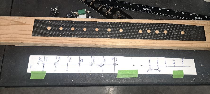
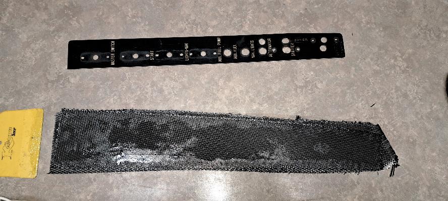
12/13/2024 - I created a new panel template, used it as a layout on the
old swiss cheese aluminum panel (see next photo) that was under
the plastic switch panel. Then I transferred the same hole
pattern to the
new carbon fiber panel.
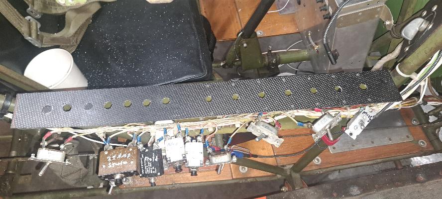
New CF panel in place over the swiss cheese panel. The old switch
guards will be removed and most of the breakers will be replaces with
more compact breakers that I have on hand.
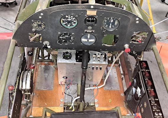
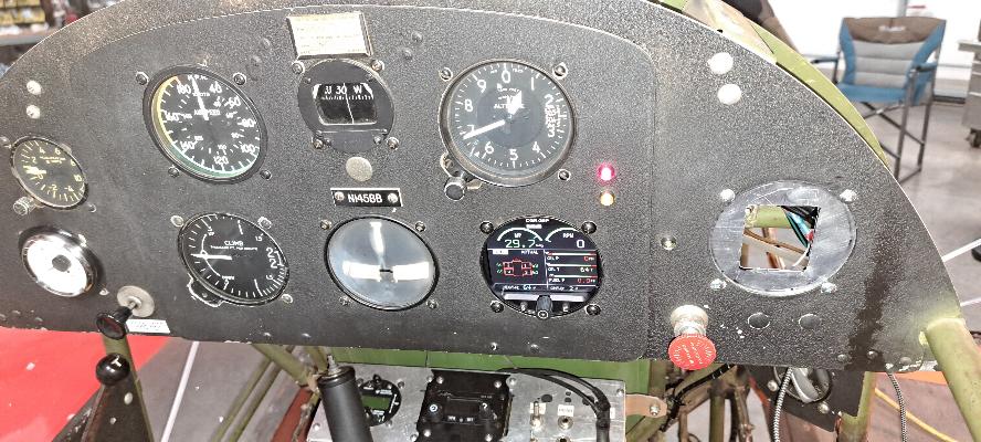
New pieces in the instrument panel so far. The white gauge on the
left lower part of the panel is the fuel gauge. Hopefully this
one will actually function in flight. The blank instrument
towards the lower right is the Electronics International, CGR-30P.
This is an all in one LED display engine monitor. I have
this installed in the RV and really like it. It offers a lot more
than I really need in this plane, but also allows me to consolidate a
bunch of engine instruments into one gauge that displays a bunch of
data, but also triggers both amber and red warning lights if something
gets out of spec with the engine.
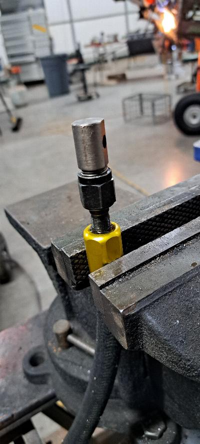
12/12/2024 - Today was mostly about fabricating new hoses for the fuel
system. This is a photo of the mandrel in use driving the
inner
part of the fitting into the steel braid hose. Yes,
the hose is contains a steel braid and with neoprene on the
inside, another layer or neoprene outside of the steel braid, then a
cotton braided outer cover. It is very stiff, but flexible.
These hoses needed to be made up to do the additional routing of
the fuel system to include the fuel flow transducer.
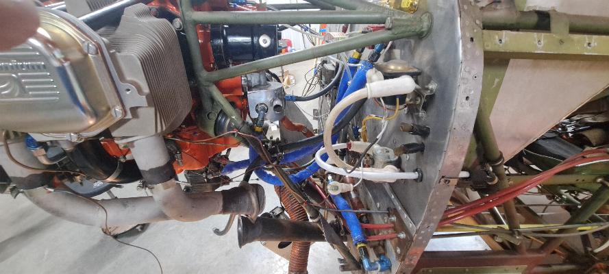
All the hoses with blue firesleeve are new. Starting at the lower
corner of the photo, the hose runs from the fuel shutoff valve to the
electric fuel pump. Next to the electric fuel pump is the
gascolator (water separator and fuel screen). From the gascolator
there is an orange firesleeve hose that runs to the mechanical fuel
pump. The output of the mechanical fuel pump runs up to the red
block hiding behind the engine mount that is the fuel flow transducer.
From the fuel flow transducer, the line runs down to the
carburetor fuel inlet underneath the engine.
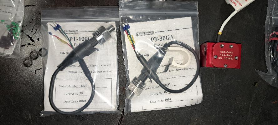
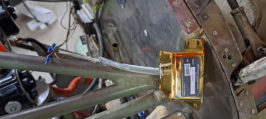
These transducers also get installed. The PT-100 is the Oil
Pressure transducer, The PT-30 is for fuel pressure, and the red block
is the fuel flow transducer. The gold colored transducer below is
the manifold pressure transducer.
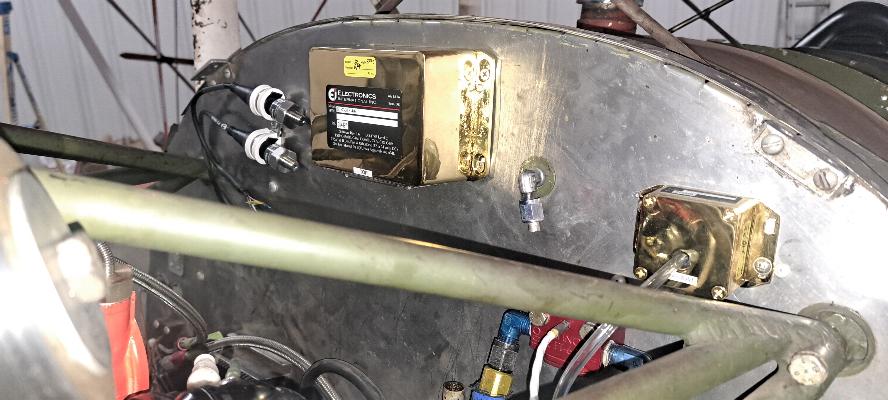
I mounted the oil and fuel pressure transducers to the firewall (left),
the manifold pressure transducer (right), the fuel flow transducer (the
red block) and the EI data module (top center) to the
firewall. I had some of these mounted yesterday, then it occured
to me this morning that once the plane is back together, the nuts on
the back side of the firewall will not be accessible. So, I
spent the morning riveting nutplates into the firewall. All
these transducers feed data to the EI CGR-30R engine monitor
display.

12/16/2024 - Today was about connecting and tidying up the wiring for
the engine monitor. All the brown wiring in the photos above and
below is Thermocouple wiring. 4 EGTs, 4 CHTs, Oil Temp, Outside
Air Temp, and Carb Inlet Temp. There are a couple of white wire
buncdles just behind the master relay on the near side of the firewall
that go to the Fuel Flow Transducer and Manifold Pressure Transducer.
In the photo below, you can see two black wire bundles that are
zip tied to the top of the firewall/engine mount that go to the Oil
Pressure and Fuel Pressure transducers.

I took advantage of existing holes in the firewall that used to house
pressure lines that are no longer needed to route excess wiring behind
the firewall where it is bundled, then enough wire pulled back through
the firewall to route around the engine as necessary. There is
still more wiring to pull, splice and mount for the engine monitor, but
this is the bulk of it. I do still need to pull a data line from
the data module to the display, and another line to monitor the
voltage. I need to find a place to install the shunt for the
ammeter and pull the wiring to the shunt. There is a bunch more
wiring work to do that I'm not quite ready for yet, so there's still
more to come on that.

This is the carbon fiber switch panel I fabricated. There are 7
switches and 5 breakers. In order the switches are Master,
Starter, Aux Fuel Pump, Avionics, ADSB/GPS/USB ports, Nav Lights, &
Strobes. I rearranged the layout and order of the switches, so
all the wiring below the switch panel is cut loose. Some wiring
will need to be added and some other wiring replaced. When
completed, it will all get zipped up tightly in place. I broke
the USB port for my GPS while pulling the wiring from it, so had to
order a replacement. It won't be in until this weekend.

12/17/2024 - Not much to show photo wise today. I have all the
switches and breakers in the right side console now. I still need
to tidy up the wiring a bit under the console and replaced the USB port
that I broke, otherwise it's done.
Small change to the front panel. Again, not much to show, but
took hours of fiddling around. The electric tach that was in the
right side of the cockpit was removed and the mechanical tach from the
back panel was to be installed. Then I had a small interference
problem where the angle drive on the back of the tachometer was going to
rub on one of the center section braces. No problem, I'll just
swap it with the airspeed indicator. Easier said than done.
Now I had some challenges with whether the new tach cable would
reach. It did with some different cable routing. Then the
pitot and static lines to the back of the Airspeed Indicator didn't
reach. I found that I had all the right stuff on hand to extend
or replace the lines as needed to make everything fit. But it
took a lot of fussing around and searching through my parts bins to get
it done.
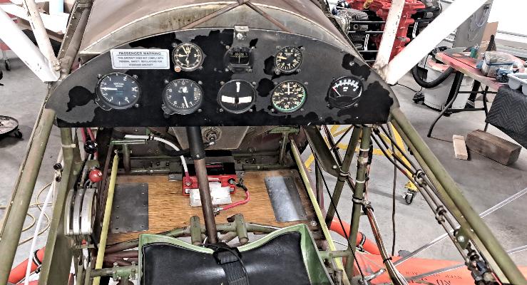
12/18/2024 - Today I completed the switch and breaker mods to the side
panel and tidied up all the wiring. Below you can see the CGR-30R
Engine Monitor from Electronics International is finally lit up.
The 3-1/8" hole to the right with a square hole in the filler panel is
cut to fit the trim indicators. I'll be redesigning the trim
system and adding servo controlled trim tabs to the tail next.

12/24/2024 -Christmas Eve... Today's goal was to wire in the
switches
for the new stick grips. The switches on the stick control
elevator
trim, radio transmit, and intercom transmit and all are active from
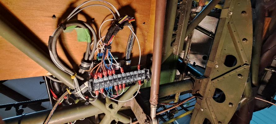
either seat. I decided to add a terminal block under the
right rear
floorboard along with the relay deck for the trim servos that came with
the stick grips to enable the trim servos to be controlled from either
seat. You can see the relay deck just under the wiring connected
to
the terminal block. I still need to pull a ground wire, +12V
wire, and
the two servo leads to complete this part of the installation. I
also
need to wire in the trim indicators in the instrument panel. I
failed
to take a photo, but today I also fabricated a new panel mount for
the trim indicators and painted it black. It will show up in
the next
round of wiring when I install the indicators. I'm waiting for
some
mini-Molex connectors to arrive to complete the connections, although I
can pull the wiring to the tail yet. The connectors should arrive
on Saturday.
12/26/2024 - The trim indicators are temporarily mounted in the left
side of the panel. I just need to replace the clecos with screws.
The terminal block under the floorboard is completed.

I'm waiting for crimp on ferrels for 24 gauge wire connectors and
mini-Molex connectors so I can complete the wiring for the elevator
trim servos. This stuff should all be here this weekend.

I started stripping the fabric from the aft fuselage so I could route and attach the wiring for the elevator trim.
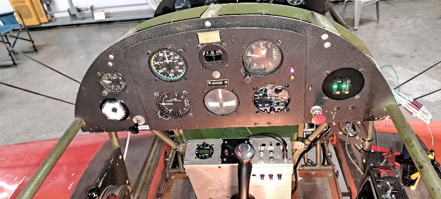
12/29/2024 - The connectors I've been waiting on arrived in
yesterdays mail, so I've now completed all but the installation of the
fuel tank sending unit for the electrical/electronics work to be done
on the plane. Now I have the trim indicators mounted and lit up
on the right side of the panel. Compare this cockpit photo of the
finished rear cockpit to the photo below from before I started.
Also compart the switch/breaker panel on the right console to the finished panel below.