2024 - 2025 Fuel System Modifications
Engine overhaul
Electronics/Electrical
Fuel System
Trim System
Fabric Recover
Items #2 & #3 from the Rebuild page: Inadequate fuel
quantity. A thirsty O-360 with only 20 gallons of fuel doesn't
give a slow plane much range. I want to work out a design to add
some fuel to the upper center section.
Fuel quantity indicator. It had a float and stick indicator like
a Cub. That's fine if it works, but on this plane, the float hit
the back of the tank and the stick was not nearly deep enough to
measure the lower half of the tank. Not very useful if it only
measures the top half of the tank. I replaced that with a
hydrostatic fuel gauge that measures the head pressure of the fuel.
That worked fine on the ground, but as soon as I start the
engine, it would go full scaale to indicate full all the time. So, now I'm changing to a
float type fuel gauge.
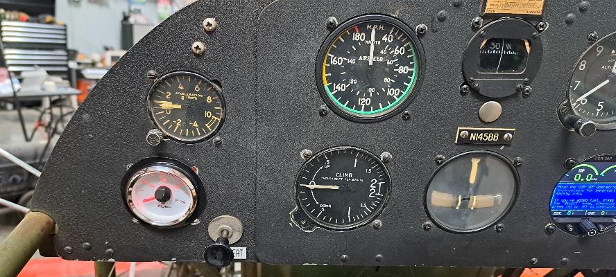
12/18/2024 - Installed new fuel gauge in the panel.
New float type sending unit to go into the tank with Molex connector for wiring.
This is currently the only fuel tank in the plane. It holds 20
gallons of fuel. With an O-360, that's 10 gallons/hour at cruise
in a plane that only cruises at roughly 100 kts. With a 30 minute
VFR reserve, that only gives me a 150 nautical mile range for
planned fuel stops, which is very limiting.
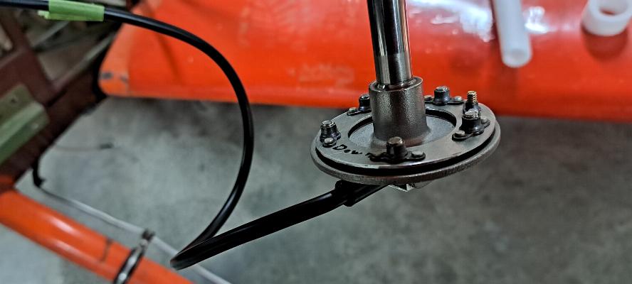
I'll need to cut a hole in the top of the tank to install this unit.
I fabricated the clamping flange you see screwed on in the photo above to go inside the tank to allow
me to clamp down onto the top. I'll seal it with some ProSeal
when it goes on. The one small cad plated screw in the clamping
plate is there to hold the plate up to the top of the tank while I
insert the unit into the tank and run in the rest of the mounting
screws. This may require a second screw and nut plate when I
install it. We shall see...
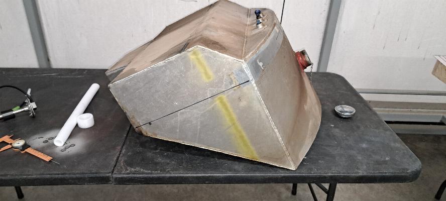
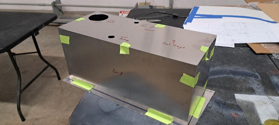
1/4/2025 - The fuselage tank is now out where I can work on it on the
table top. The line on the side is where there is an internal
edge at the bottom of the tank that I have to miss with the fuel probe,
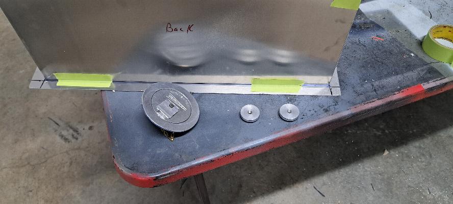
so I need to be in front of that line. The line on the top of the tank
(see below) is where the limit of where the back edge of the hold down
strap will fit. I've got a pretty tight spot to fit this all in.
This is what is left of the backing flange I made to go inside the tank
to bolt the fuel probe into place. The small phillips screw at
the left holds the internal mounting flange up to the inside of the
tank so I can run in
the screws that clamp the probe down to the top of the tank.
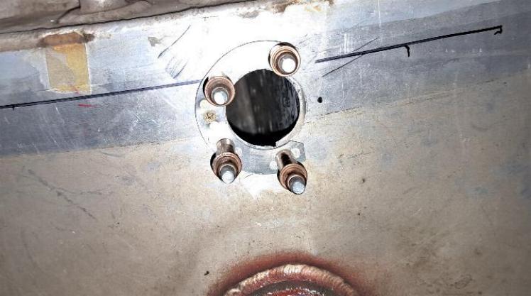
Here's where I made a mistake that made things a bit more
difficult. When I cut this hole with my hole saw, I cut right
into a vertical divider that runs down the middle of the tank.
Oops! The divider is visible through the hole in the photo
above. That's why the hole all the way to the right is not
drilled yet and I had to cut down the backing flange. I cut
the backing flange to butt up against the internal bulkhead.
Since
there are two relatively thick layers of aluminum where the bulklhead
buts against the top of the tank, I drilled and tapped
the hole to the right through the tank and bulkhead and used that to
hold down the fifth screw rather
than a nut plate like the other 4 screws.
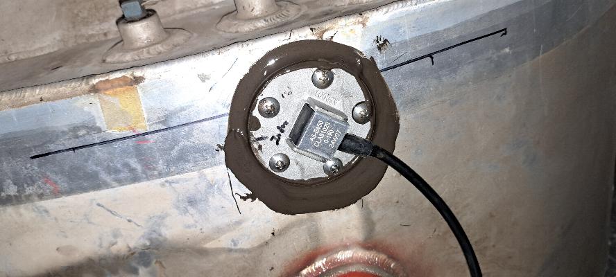
The backing flange is now mounted inside the tank with the countersunk
screw holding it in place under the mark where I have "Index" marked on
the top flange. All but the one screw all the way to the
right are run into nutplates that are riveted to the flange backing
plate that is inside the tank.
The screw on the far right side of the flange is threaded into
the top of the tank and the top of the internal baffle. It is all
sealed with a generous bead of ProSeal underneath and a finger fillet
of proseal around the flange from where it squeezed out.
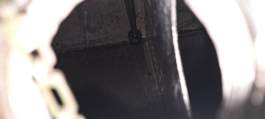
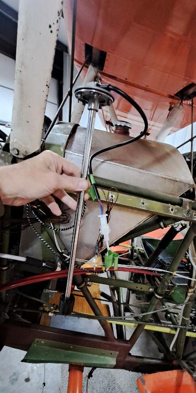
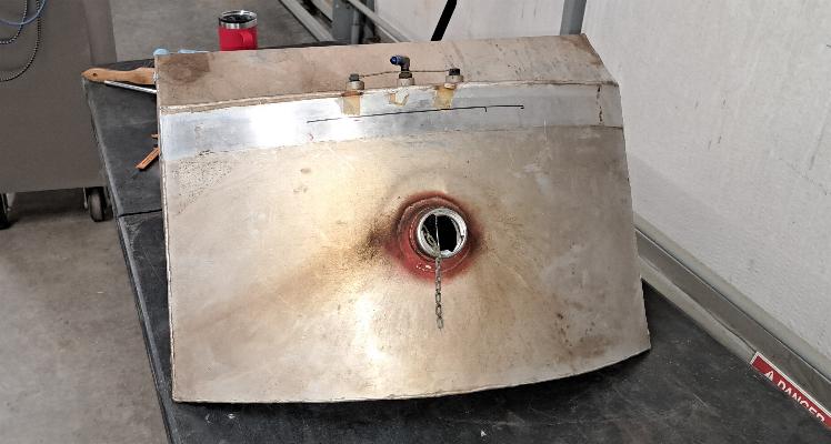
This photo is looking down through the filler neck. You can see
the fuel probe just missing the back of the tank and just missing the
perforated bulkhead to the right. The black slider at the bottom
of the shaft is the float that floats up and down the shaft where it is
sensed to indicate the fuel level.
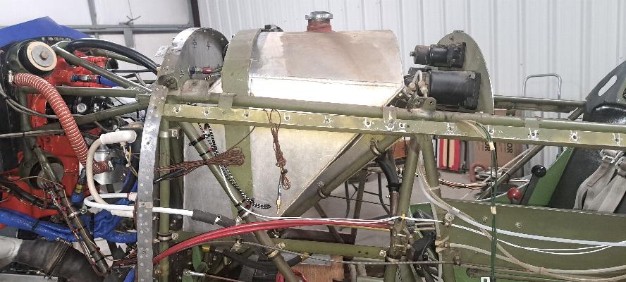
1/7/2025 - The main fuel tank is now re-installed in the airframe.
That's the first part to go back onto the plane that had been
removed, so is the first step towards reassembly. Only about
100,000 steps left to go! It is possible the bump on the top of
the fuel probe may interfere with the top of teh boot cowl. If I
does, I'll cut an access hole and raise the cover 1/8" to allow it
sufficient room.
The plan is to design and build an additional fuel tank into the upper
center section, then refuel the lower tank from the upper tank by
opening a valve to allow it to drain. I hope to get 8 - 10
gallons into the upper tank, which would extend my range by an hour;100
nautical miles. The volume will depend on how much room I can
find in the center section. It has cross braces that go through
the middle of the center section, so I need to either move the cross
braces and re-enforce the center section with plywood, or build some
custom tanks to fit around the cross braces and plumb them together.
I'm leaning away from doing structural modifications to an
aerobatic plane. I'm not an engineer and don't feel that I'm
qualified to analyse all the stresses the center section sees.
So, I'm leaning towards fabricating some custom shaped fuel cells
around the cross braces and plumbing them together. I'll start
developing a more mature plan once I have the center section off on the
bench and get the fabric off.
1/25/2025 - I spent about a month and a lot of $$ building a carbon
fiber/fiberglass tank with vinylester resin. I've done this
successfully before, but had some serious technical challenges in
fabricting the tank to bridge over the internal cross braces in the
center section. Ultimately, it leaked and was really
unrepairable. Bad design work on my part and poor construction
technique as well. I cut it all out and trashed it, then
moved on to another plan.
Repairing the center ribs and reinstalling them in the center section.
I left the reinfoced ribs that supported the tank in place for
the other two internal ribs. I would have had to destroy the ribs
to remove them. Not worth the effort to save a few onces.
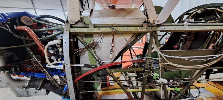
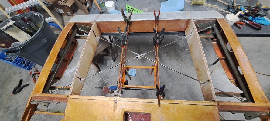
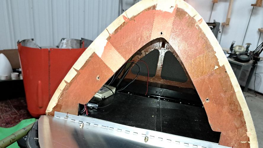
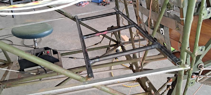
1/28/2025 - I've not completely given up on the idea of an auxilary
tank. I'm considering building a tank inside the baggage
compartment shown above. I would only use the bottom 8" of the
baggage area, which would make an 8 gallon tank, leaving a small
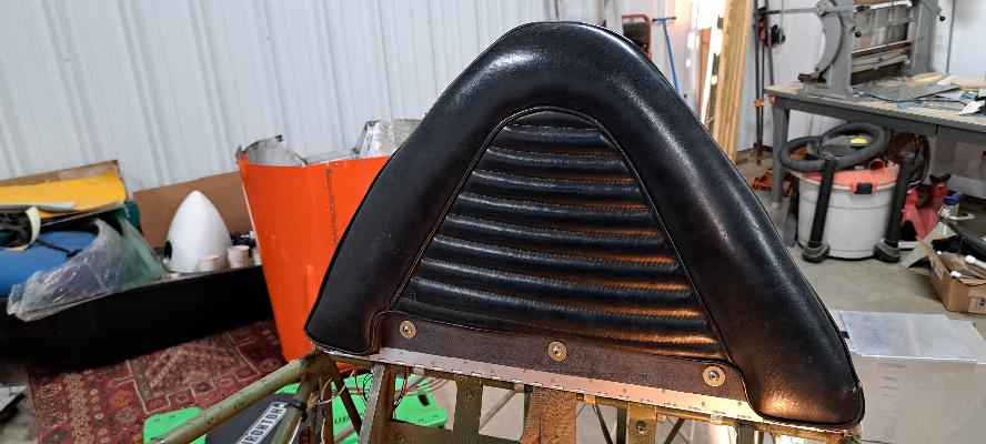
baggage area above the tank. Additionally, I would add a bottom
and back into the turtle deck (shown below), then hinge the headrest at
the bottom for ready access, making for a second readily accessible
baggage compartment. I've not made a decision on this yet, but am
mulling it over.
3/6/2025 - After weeks of doing engine work for others, I'm back to my plane
again. I have made the decision to have a local welder weld an
aluminum tank for me. Why? There is a lot of uncertainty
about the future of 100LL, and the G100UL candidate to replace 100LL is
currently getting a lot of negative press regarding degredation of
paints and composite parts. With 10:1 pistons in the engine, this
plane will require 100 Octane fuel. So, to be on the safe side, I
made the decision to build the aux tank with welded 5052 aluminum.
The first thing to do was to consult with the local welder.
We agreed to fabricate this using a bottom plate of .063" that
will mount to the same tabs where the baggage compartment used to
mount. This bottom plate will become the mount for the tank.
The rest of the tank will be constructed using .040" 5052.
Interesting that I can order 2x3' sheets of 5052 on Amazon
relatively inexpensively.
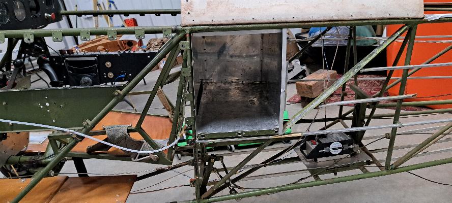
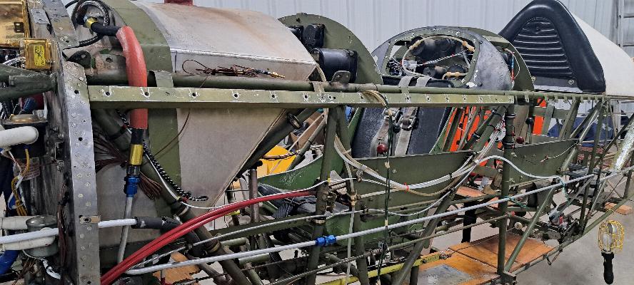
The baggage box is now out of the airframe. Interesting that they
had to bend it to get it into place, then rivet the back of the box in
so it would retain it's shape.
This is where the baggage box used to be. The aux fuel tank will get mounted into here.
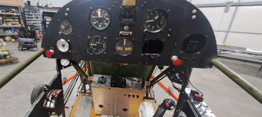
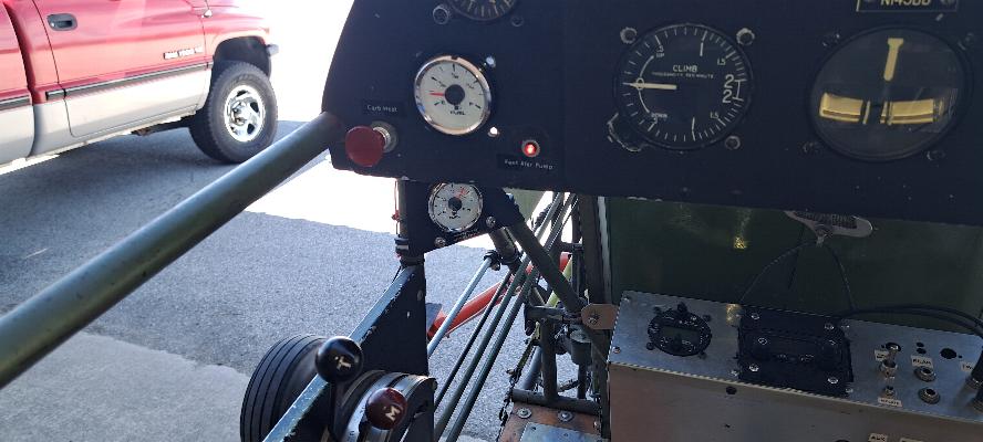
I started to install that little cutout under the left side of the
instrument panel as a place to mount a fuel gauge for the Aux Fuel
Tank. However, the carb heat cable was already kinked against a
tube with it mounted to the right of the current fuel gauge. With
the little mini-panel under the left side, there was a second kink in
the carb heat cable and that ruined the cable. I had a new cable
on the shelf, so moved the cable to the far left side of the panel to
eliminate one sharp turn in the cable. Then I did an offset grind
on two washers on either side of the panel so I could mount the cable
with the backside pointing downward a bit so I could eliminate the
sharp curves in the cable. It works better than ever now.
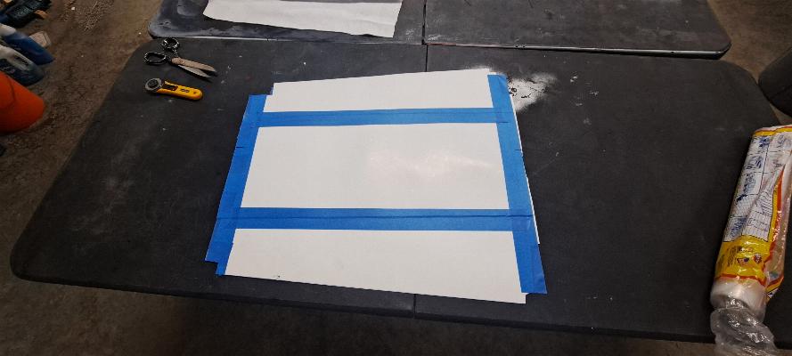
Next up was to fabricate a template for the floor of the new baggage
compartment. The way it fits, it will have to go in as two pieces.
I have the better part of a gallon of vinylester left over from the
previous attempt at building a fuel tank, so decided to use it with
carbon fiber to fabricate the floor and back of the baggage
compartment. VinylEster has a limited shelf life once it has been
promoted to be sold, so this stuff needed to be used anyway as it will go bad before summer. So,
I had the vacuum pump running much of this week while I fabricated
several small pieces from carbon fiber.
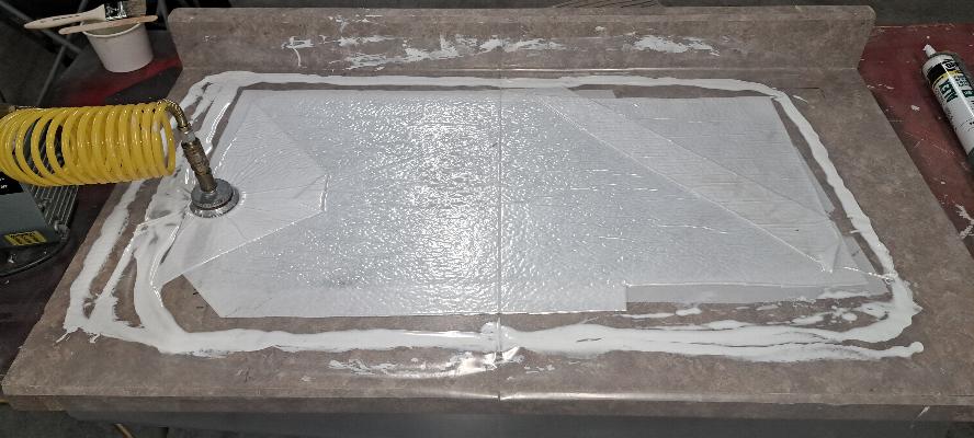
This is an example of how I do vacuum bagging if I am making flat
parts. I lay up the part on a piece of waxed formica countertop,
add a piece of peel ply (dacron fabric), then some felt to absorb
excess resin, then cover with plastic sheet cut from the cheap painters
plastic drop cloth you can buy at Walmart. Then I use the
cheapest caulking I can find and run a bead of caulking around the part
and slap the plastic down over it. Plug in the inexpensive
medical grade vacuum pump, let it cure and you have a vacuum bagged part.
Contoured or molded parts require some more expensive bagging materials,
but if I'm making a flat panel, there is no need to waste my money on
the expensive bagging materials.

This is the baggage compartment as fabricated. You can see the
seam of screws down the middle to hold the two halves of the bottom
together. They are also anchored together with some vinylester
resin as well. There is a black aluminum angle half way back in
the baggage compartment. I'll attach a baggage net to prevent
larger or heavier things in the baggage copartment from migrating to
the back of the compartment. Think in terms of what might happen
while going straight up in a hammer head. Everything in the
baggage is going to try to go to the back, then while coming straight
down, it might very well come slamming forward into the front of the
compartment. I want to keep a bit better control of the stuff in
there.

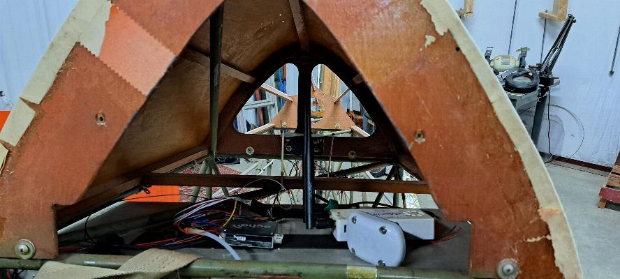
I peeled the upholstery of the old headrest off the aluminum plate it
was mounted to and bonded it to a plywood panel. That panel will
be hinged at the bottom with a piano hinge to tip the headrest forward
to access the baggage compartment. Previously it was bolted in
place. I added a carbon fiber panel to the bottom of the headrest
to close up the baggage compartment. The headrest isn't mounted
yet. Only the piano hinge is mounted to the airframe. The
rest is just sitting in place to see how it looks.
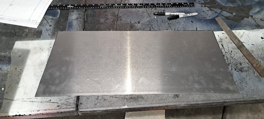
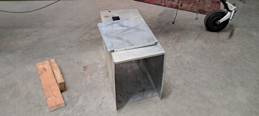
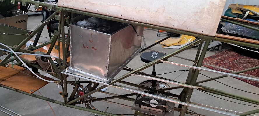
This is the .063" 5052 aluminum base for the fuel tank. I'll
mount it into the airframe and on the mounting tabs for the old baggage
compartment, then will build the rest of the tank onto this plate. The rest of the tank will be .040" 5052 Aluminum.
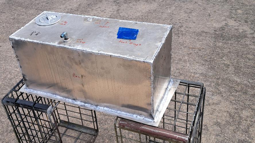
3/8/2025 - I completed cutting out the pieces to fabricate the fuel
tank. It's held together with masking tape for now, but all the
corners are tight enough that it shouldn't be a problem from the
welder. I have one welding flange with 1/8" NPT thread to go into
the bottom of the tank to be the fuel drain. I have another
flange with 1/8" NPT that goes in the top towards the front that will
be the tank overflow/vent, and another welding flange that goes towards
the back of the tank on the top for the fuel pickup. The big hole in the top is for the
filler neck. I don't have the fuel gauge transducer yet, so I
ordered a gasket for it that I'll use for a pattern to mark the tank
penetrations, then will rivet in the nut plates to mount the gauge.
The gauge won't be here until the end of the month, but once the
nut plates are installed, I can take this tank to the welder to be
completed.
You can see in the photo above that there is a substantial flange
around the bottom of the tank. The tank will be mounted by that
flange. However, I will also add some padded steel angle under
the tank to help support it.
Filler neck and two of the welding flanges.
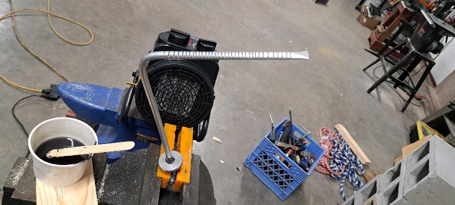
Bonding the 3/8" fuel pickup tube into the bottom of a AN822-6D fitting
that is screwed into the 1/4" NPT thread in the welding flange.
3/9/2025 - Added the USB charger outlet and electronics into the
baggage bay. I have an Echo UAT ADSB In and Out unit, and a
Stratux ADSB receiver as a backup device.
The headrest is now attached to the piano hinge and closes off the
baggage access when it's up. I'll be adding a cabinet lock to it
to make the baggage area lockable.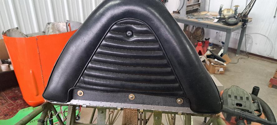
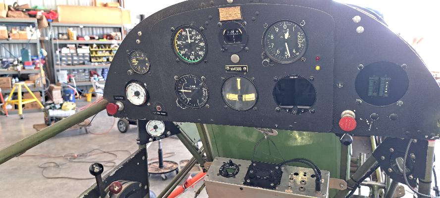
3/13/2025 - Added new gauge for the aux fuel tank to the
lower left below the panel. I also added an indicator light just
above the gauge to indicate when the transfer pump is running to
transfer fuel to the main tank. I also installed the lock into
the headrest, but forgot to take a photo. I'll get that tomorrow.
3/15/2025 - I fabricated this mount to go under the new fuel tank.
The fuel tank is still with the welder. I'll check on it
Monday. The mount obviously will need to be primed.
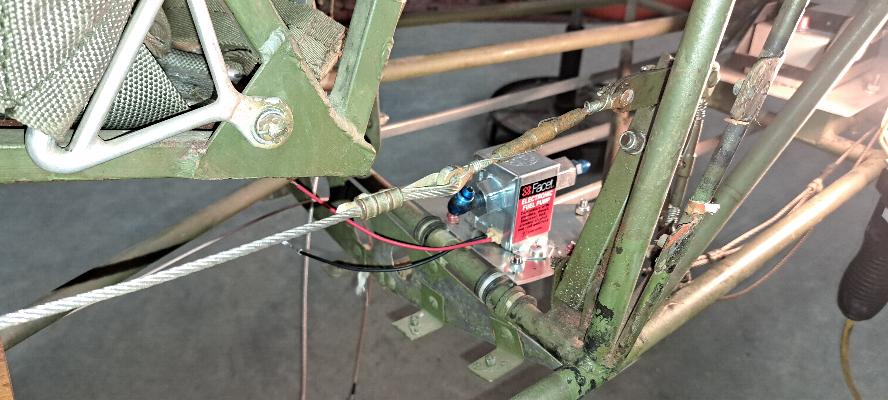
3/18/2025 - Installed fuel transfer pump for the Aux Fuel Tank.
I'll start running the plumbing to the front tank tomorrow.
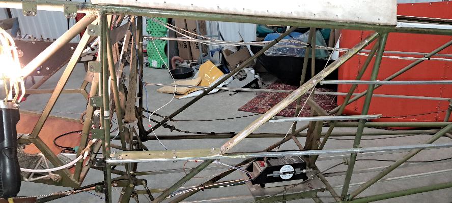
3/19/2025 - I routed the 3/8" aluminum fuel line from the fuel transfer
pump in the rear up to the top of the main fuel tank in the front.
In this photo, it is easily identified by the orange firesleeve
protecting the fuel line where it lays on the ongeron just in front of
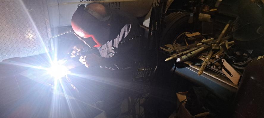
the main fuel tank Below, the welder is slaving away melting
aluminum TIG welding the new aux fuel tank. Hopefully he can
finish it tomorrow so I can leak check it.
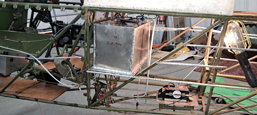
3/21/2025 - I got the fuel tank back from the welder this afternoon.
This is the leak test with it full of 100LL. It holds 9 gal
of fuel, which should extend my air fime from 1-1/2 hours to 2-1/2
hours plus VFR reserve. I should be able to go somewhere with it
now.
I had predrilled the bottom flange of the tank as well as the mounting
frame that's underneath to fit onto welded tabs in the fuselage.
All had been carefully fitted and fit perfectly. I failed
to remember how badly sheet metal, and even 4130 tubing distort from
the heat cycles of welding. When I tried to install it, nothing
fit. Not even close. I had to back up and redrill all of
the mounts, so it turned into a bit of a struggle, but I finally
prevailed late this afternoon. I still need to complete the
plumbing for the tank and it will be ready to go. Note the large
diameter flush mounted filler cap. It will be challenging, but
not impossible to refuel. Once the fuel system is completed, it
will be time to go full bore on the fabric work.
3/22/2025 - I installed the fuel pickup line, the overflow/vent line,
and the tank drain line today. I'm still missing a bunch of adel
clamps for the line running forward, and the two adapter fittings that
go on either side of the fuel pump. They should be delivered on
Monday.

3/24/2025 - I rolled the plane out for the first time since November.
The task here was to fill the Aux Fuel tank, then transfer the
fuel from the Aux Tank to the Main Tank to test the fuel transfer
system as well as time to transfer.
I started with the Aux tank full and the Main tank empty.
This also tested the fuel gauges in both tanks. Both gauges
appear to be reasonably accurate. For this picture, you can see
that I have transfered 1/4 of the Aux tank into the Main tank.
With the Aux tank holding 9 gallons and the Main 20 gallons,
these gauges appear to be just about right. The transfer time was
a bit disappointing. It took 25 minutes to transfer the 9 gallon
capacity of the Aux tank into the Main. However, that is still
more than twice the rate of fuel burn for the engine, so it's going to
have to be fast enough. I also noticed in the photos here that I
need to label the gauges as to which gauge is for which tank.