The RV-6 Rebuild project
More on Page 2
Engine on Page 3
Final Assembly on Page 4
Flight test and test flying on Page 5
February
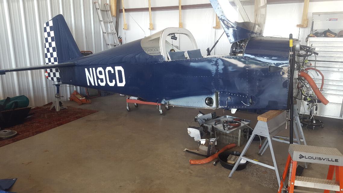
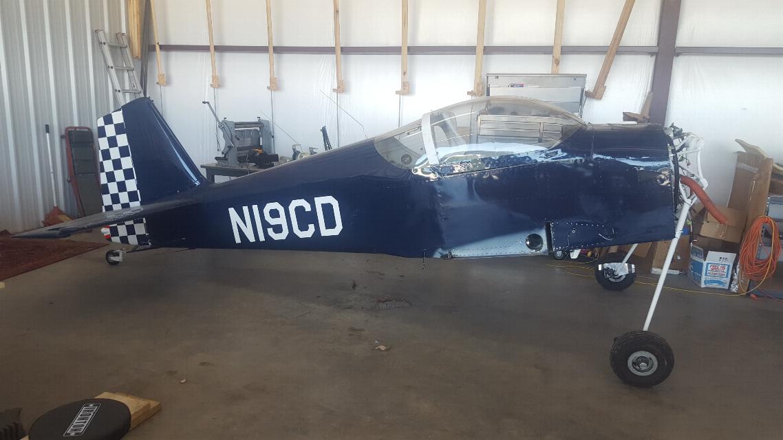
2020 - I ran across this RV-6 in Albuquerque, NM. It has been
damaged, but was priced about right, so I bought it. Not sure if
it was the right thing to do or not, but now I'm committed. At
first glance, it doesn't look too bad. But then there are all the
things I didn't know that I had to learn before I moved it.
After buying the plane, I drove home to Arkansas and started to educate
myself on what I needed to know to move this plane. It never
occurred to me that the gear bolts to the spar and isn't capable of
supporting the plane with the wings off. I learned that I was
going to need to build a false wood spar to insert into the spar slot
in the fuselage so I could bolt the gear mounts back in and the plane
could support itself on it's gear on the trailer. This is my
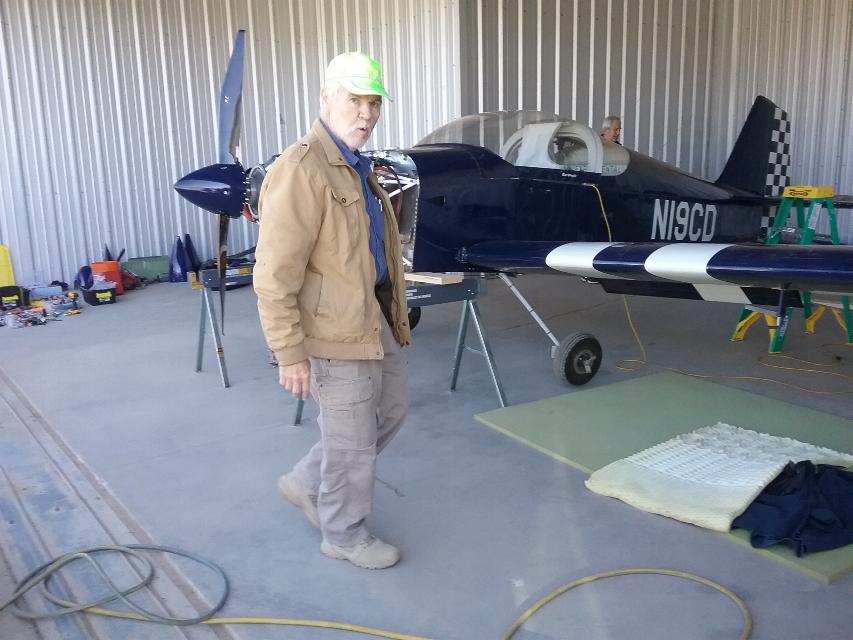
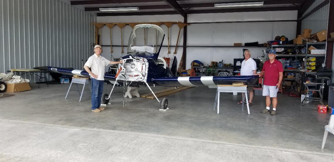
buddy Larry from Dallas. Larry's got a lot of expertise in
packaging and moving planes and is an all round creative thinker.
I should have listened to him a bit more when it came to packing
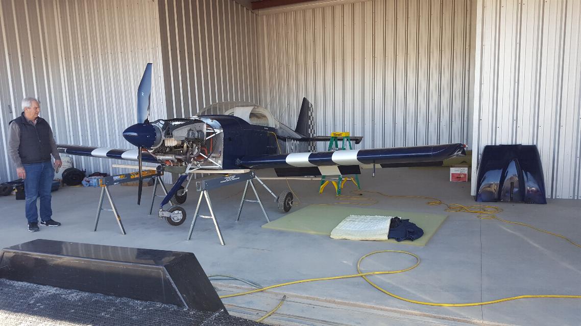
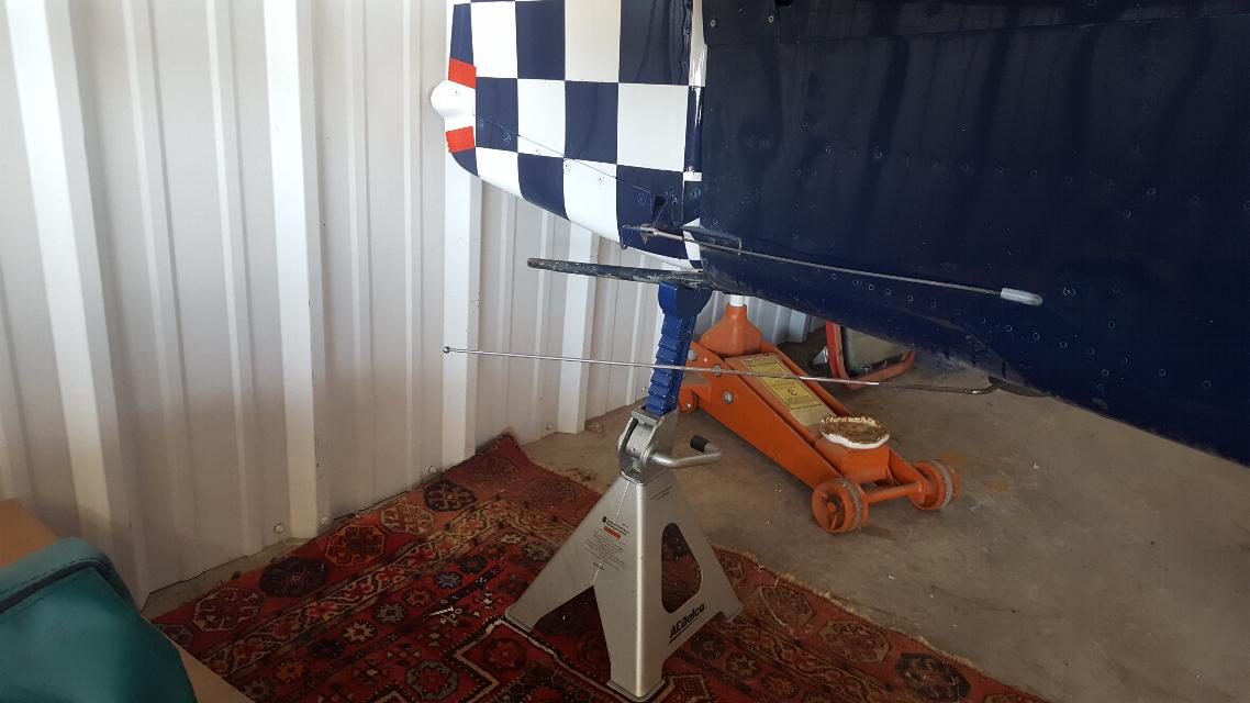
up the plane. Here we have the plane on saw horses to get the
weight off the gear so we can pull the wings.
The spars have 76 bolts through them, of which none were readily
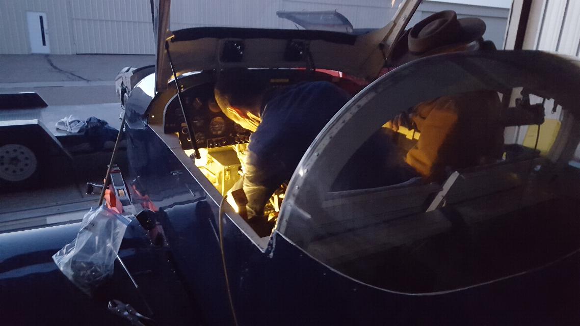
accessible. This is my long time buddy David from Santa Fe.
He did yeoman's duty folding himself under the panel working on
the spar bolts. It took two days to get them all out and to pull
the wings.
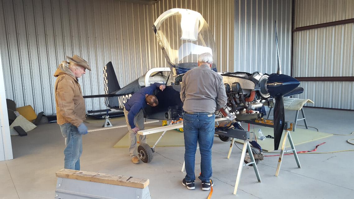
One wing off. Doug, David and Larry looking over the situation.
And the new skinny me.
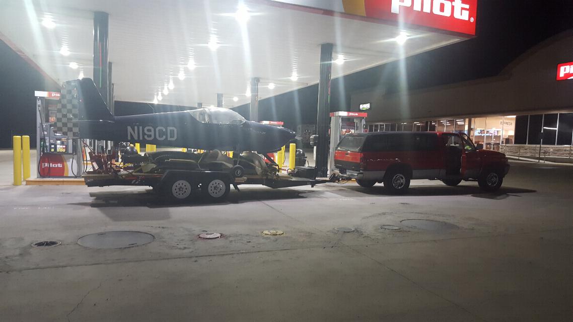
On the way home packed up on the trailer. The wings are packaged up in all that foam underneath the fuselage.
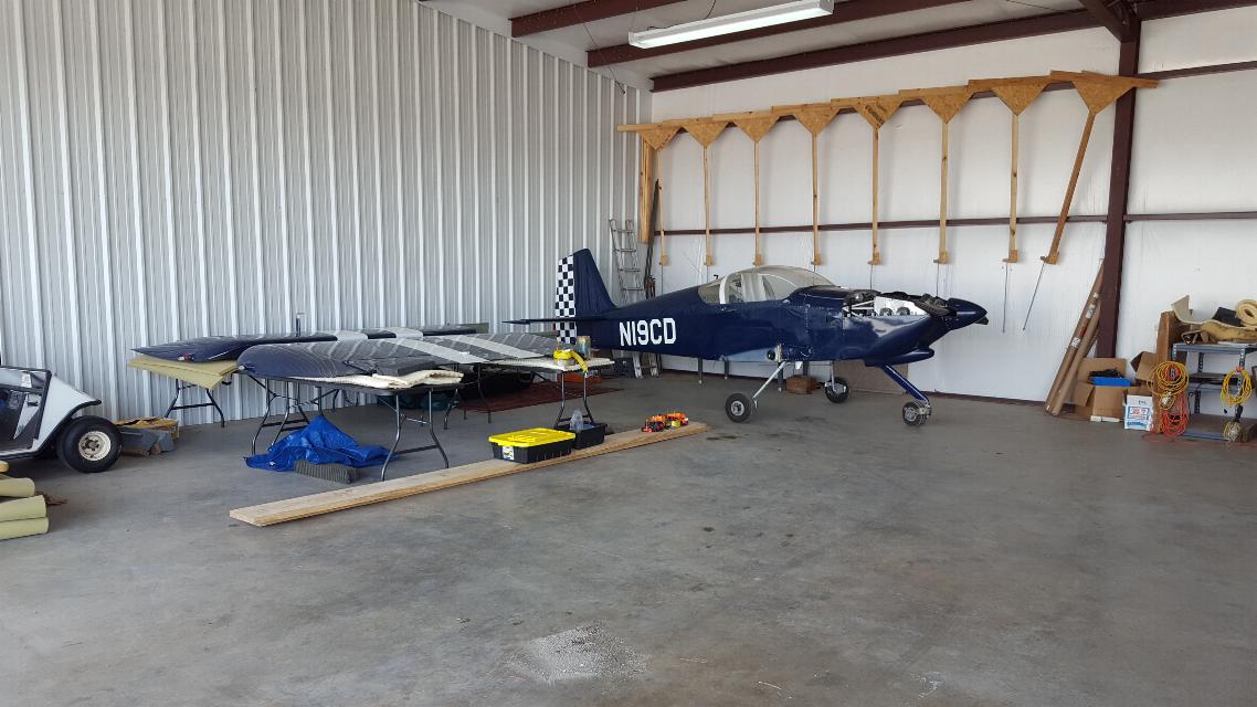
Unloaded and parked in the back corner of my hangar in Cherokee Village. (KCVK)
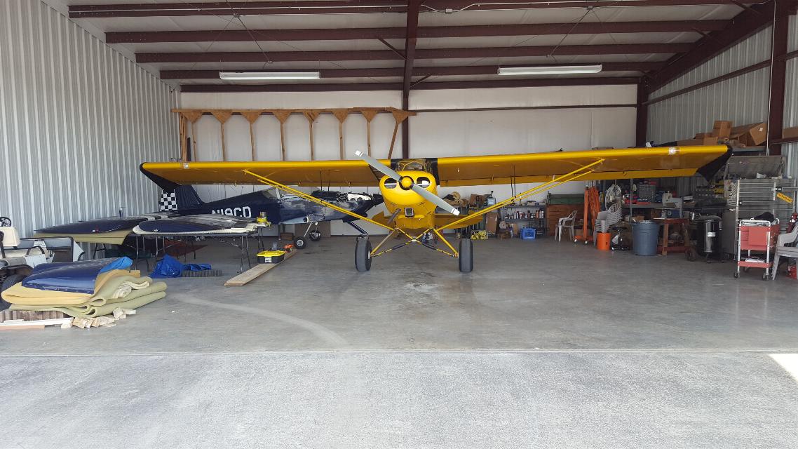
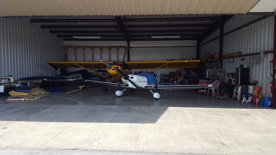
Along with its hangar mates; Mr SuperCub, and Mr KR below.
May 29, 2020 - I've spent all spring dealing with my mother's illness,
death and estate. All the while I've been chomping at the bit,
but haven't touched the RV. It's just been sitting in the back
corner of the hangar waiting for me to get to it. I finally got
caught up on all the household chores as well as the organization of my
mothers estate, so I've given myself permission to get rolling on the
RV.
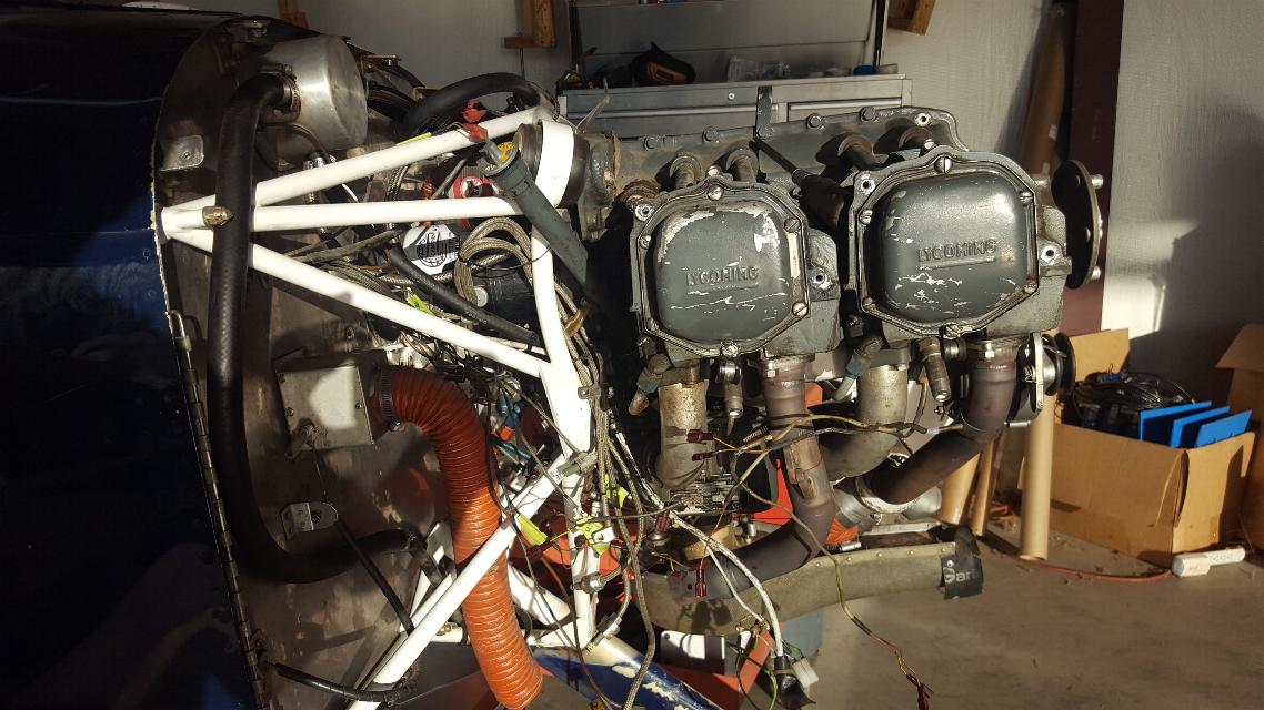
Lot's of wiring and hoses to sort out and disconnect from the
engine. Sometimes I think unmating the engine from the airframe
is as much work as overhauling it.
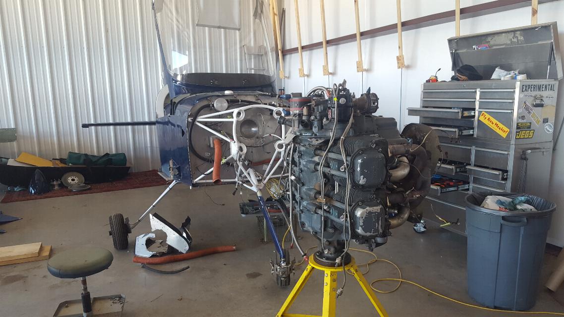
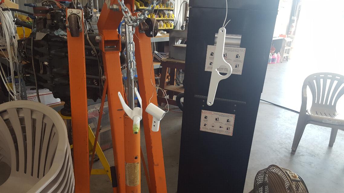
May 30, 2020 - The engine is off and onto the stand.
Glad to
have that task done. This engine has roughly 1200 hours since
overhaul, although it's difficult to know for sure as the logs are
missing. Overall, the condition is unknown. However, I do
know that it has had a prop strike and bent over a Sensenich metal
prop, so it's going to get a complete tear down inspection. I
always look for a plane with a sick or tired engine anyway, as I am
always a lot more comfortable after I go through the engine myself.
Update: A little more history came to light on the engine.
This was a new Engine purchased through Vans, so is actaully at
1200 hours since NEW. That's good news as most everything should
be in good condition inside. We'll see when I tear it down on Page 3, the engine page.
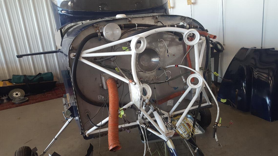
The Firewall is looking a bit cleaner without the engine hanging there.
Now on to removing the landing gear. I'm converting it back
to a taildragger again. These are the gear mounts that were
bolted to the spar and made wing removal so difficult. That's
half the reason why I am converting it back to a taildragger. I
don't like having them take up space in the cockpit, and I didn't like
dealing with them while unbolting or bolting up the spars.
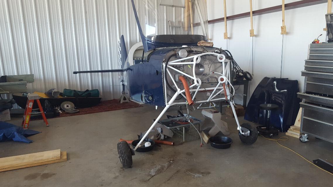
Sure looks a lot smaller without the firewall forward and the
landing
gear. Note that the engine mount is off now as well.
The new main gear will mount to the engine mount, so it gets
a new engine mount to go with
converting it back to a taildragger.
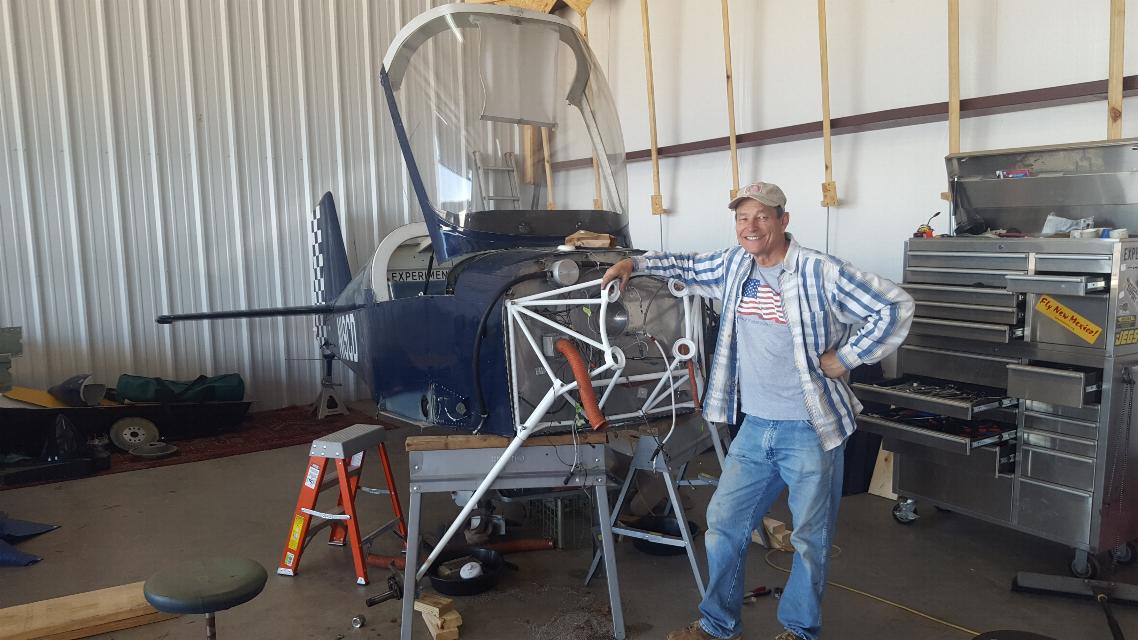
June 1, 2020 - My buddy Jim came over and spent the morning helping me
bolt the new engine mount to the airframe. It came with what was
supposed to be the right bolts, but as usual, it turned into a
reiterative process of trial and error to get the right bolts and
correct washer stacks to get everything fitted properly. Thanks
for your help buddy! Notice the theme here. This doesn't happen without a little help from your friends!
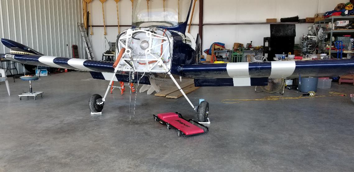
Now she's standing on her own two legs again. With them installed in the right place!
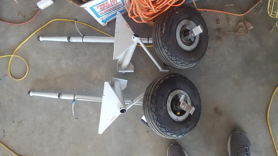
The tailwheel from the landing gear kit fit onto the old tail spring
just fine, so I took it apart and painted. It will get installed
tomorrow.
Old Tail spring. I didn't take a picture, but also painted the
tail spring before I went home for the day. New photo of it
tomorrow with a tailwheel mounted to it.
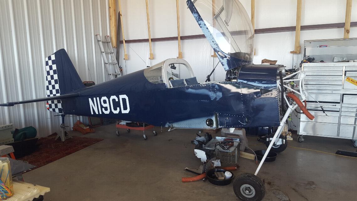
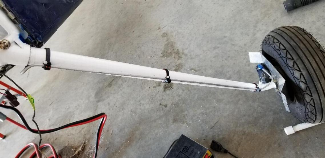
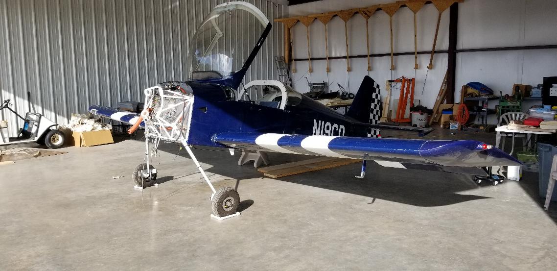
June 2, 2020 - She's sitting on the new gear now with new tailwheel installed.
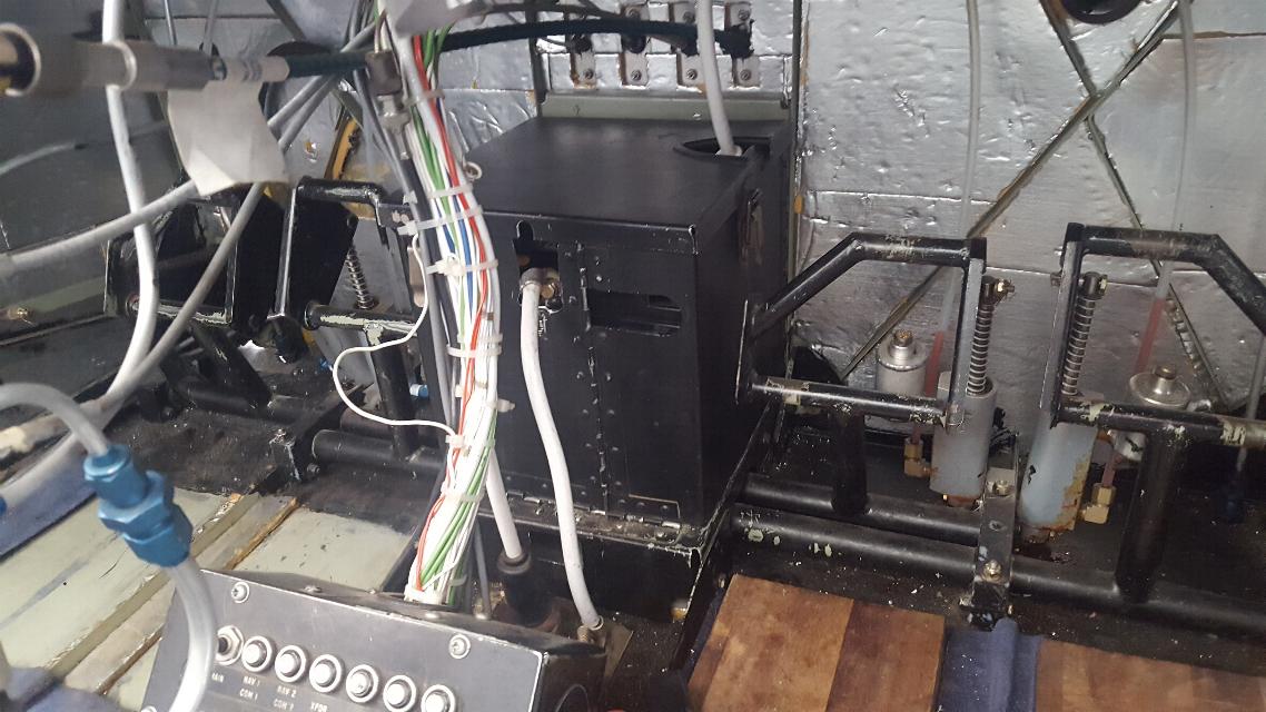
I didn't take a previous picture, but the battery box fell apart
and the batteries became disconnected during transit from NM to AR.
These things were never designed to ride on trailers.
Reassembled the battery box today and hooked up the batteries.
Notice the plural. It has a 24V system. I'm not
thrilled with that, but the avionics are old enough that they are not
"universal" voltage (9 - 32 Volt) like most newer avionics. So,
if I wanted to change it to a 12V system I would have to replace the
starter and alternator, and most of the avionics. It's going to
be easier to keep two batteries. I might think about EarthX to
lighten the battery weight a bit later on.
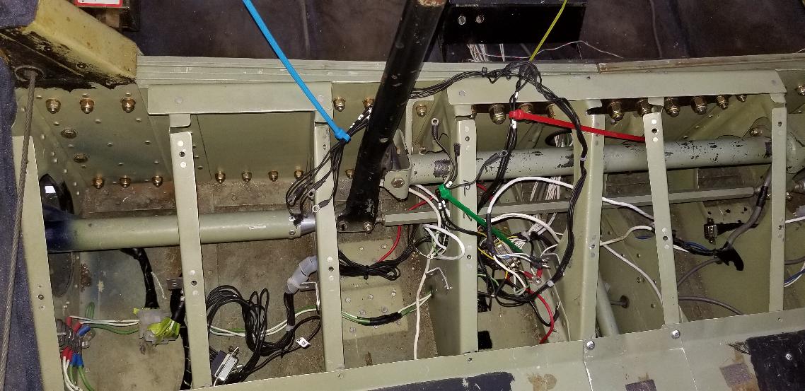
Now to sort out all the wiring that was cut to remove the wings.
Lots of testing going on here. There weren't any
disconnects for the wing wiring, so we just cut the wiring while
removing the wings.

Same on the right side. There are a few mystery wires in
here, so I'll have to dig into the wing to see where they go. And
yes, that capstan in there is the aileron servo for the S-TEC Autopilot.
Right wing tip is off. I'll have to disconnect some stuff in here and chase down the wires tomorrow.
June 4, 2020 - I sorted my way through the wiring in the wings, then
installed molex connectors for quick disconnects just in case they ever
need to be removed again.
No photos to show, but also vacuumed all the debris out of the cockpit
and cleaned it up a bit. I still need to sort out the PTT
function problem and a broken switch on the autopilot, but otherwise I
think I have the electrical issues pretty well sorted out.
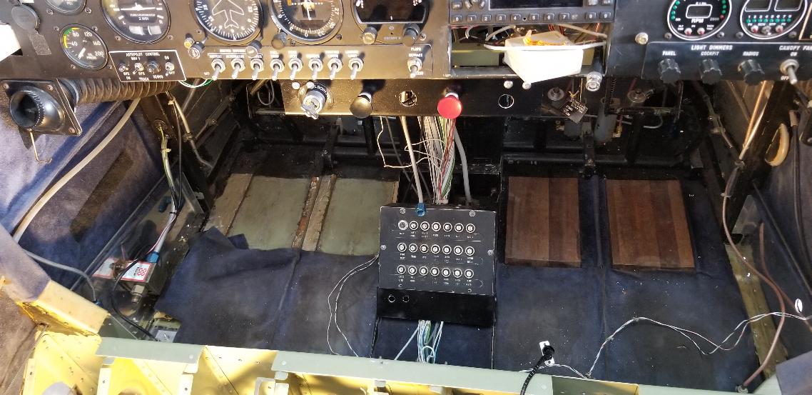
June 8, 2020 - I took a few days hiatus from the RV work and have been
flying the wings off the SuperCub and KR while I'm waiting for parts to
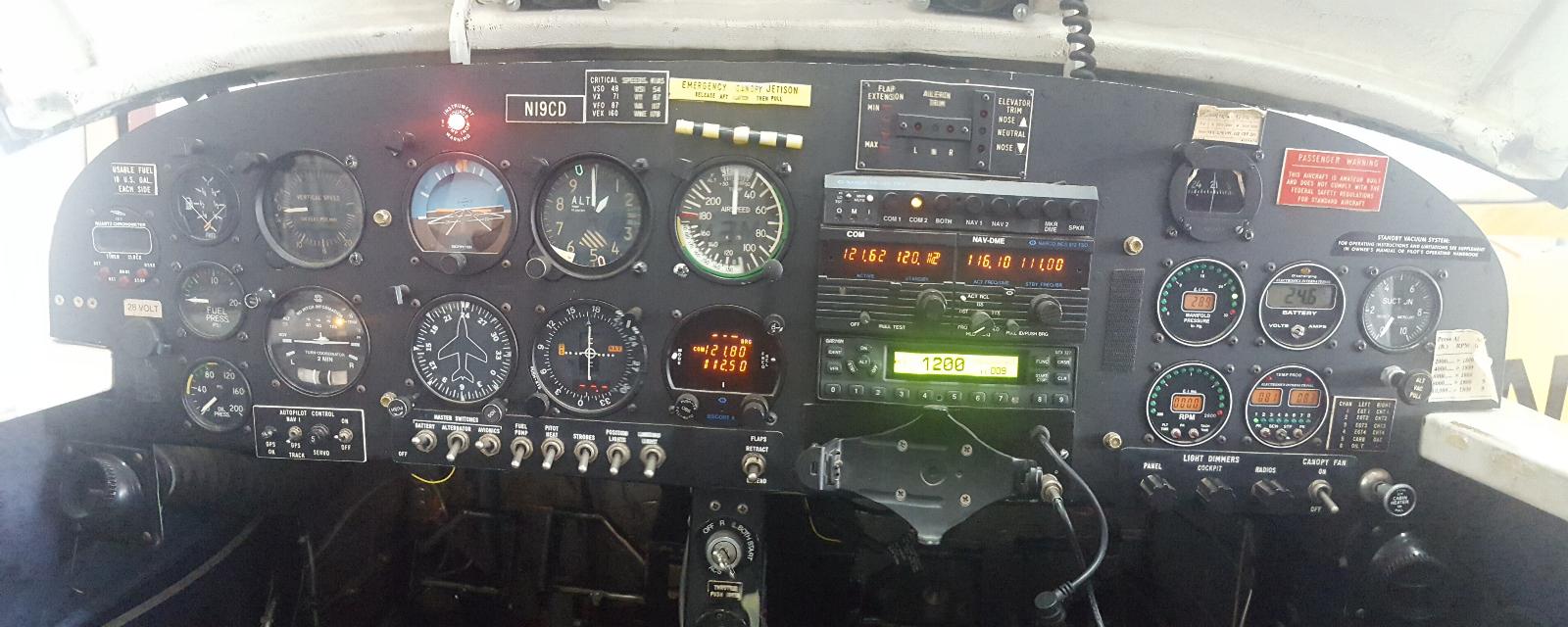
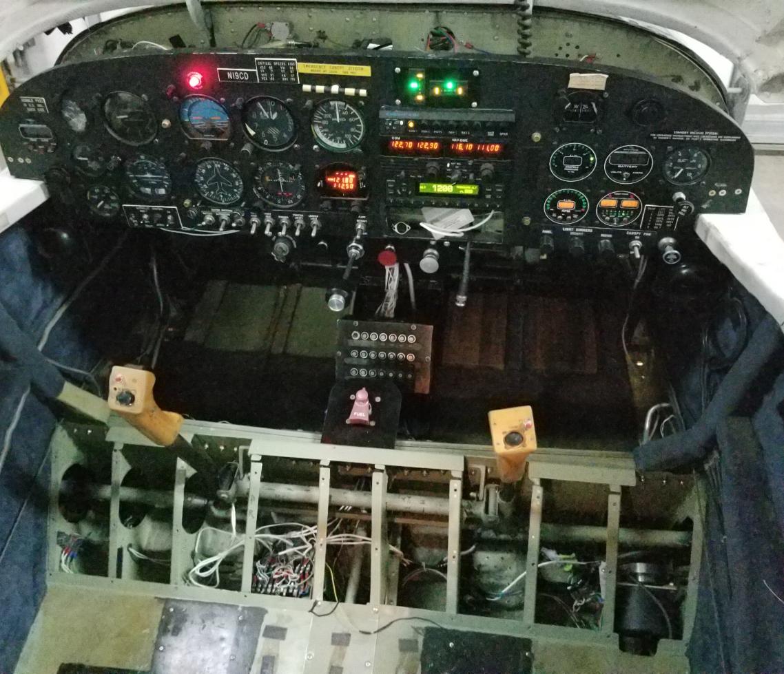
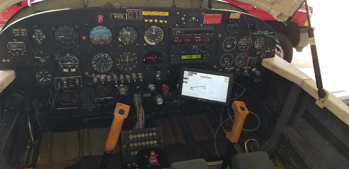
be delivered for the RV. My buddy Oscar asked for a photo of my
panel. Apparently I needed to wipe the lens on muy phone, but
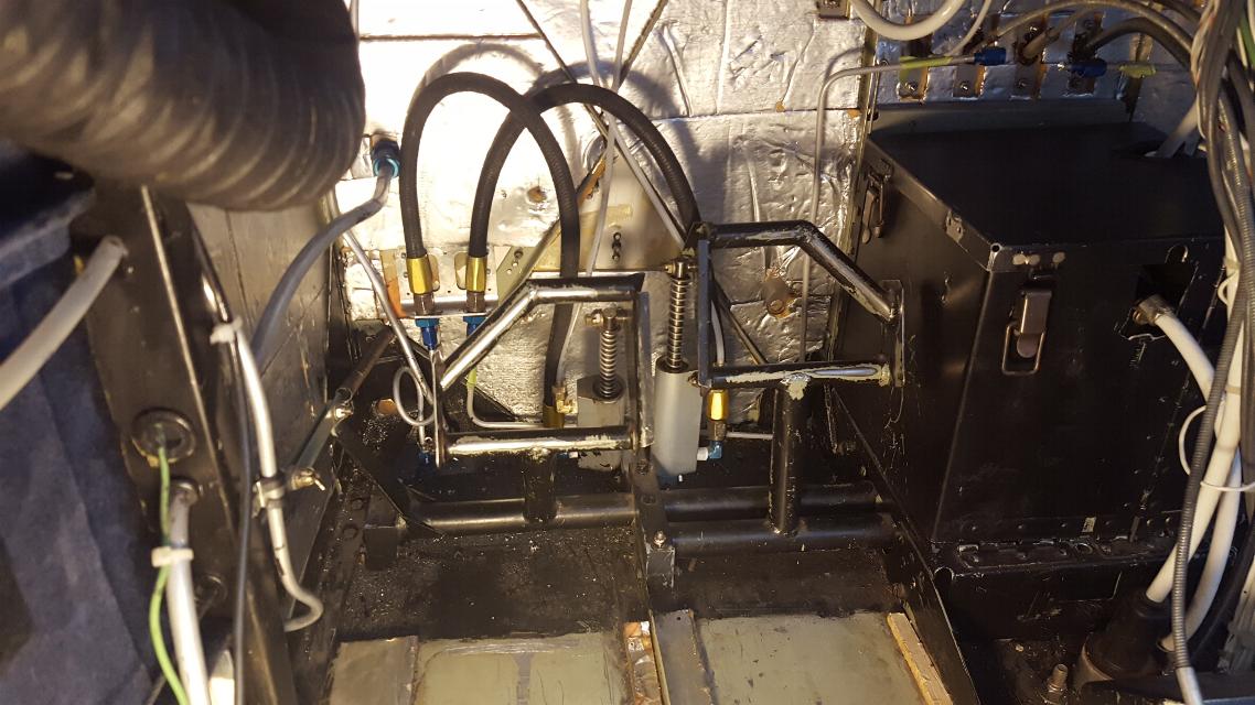
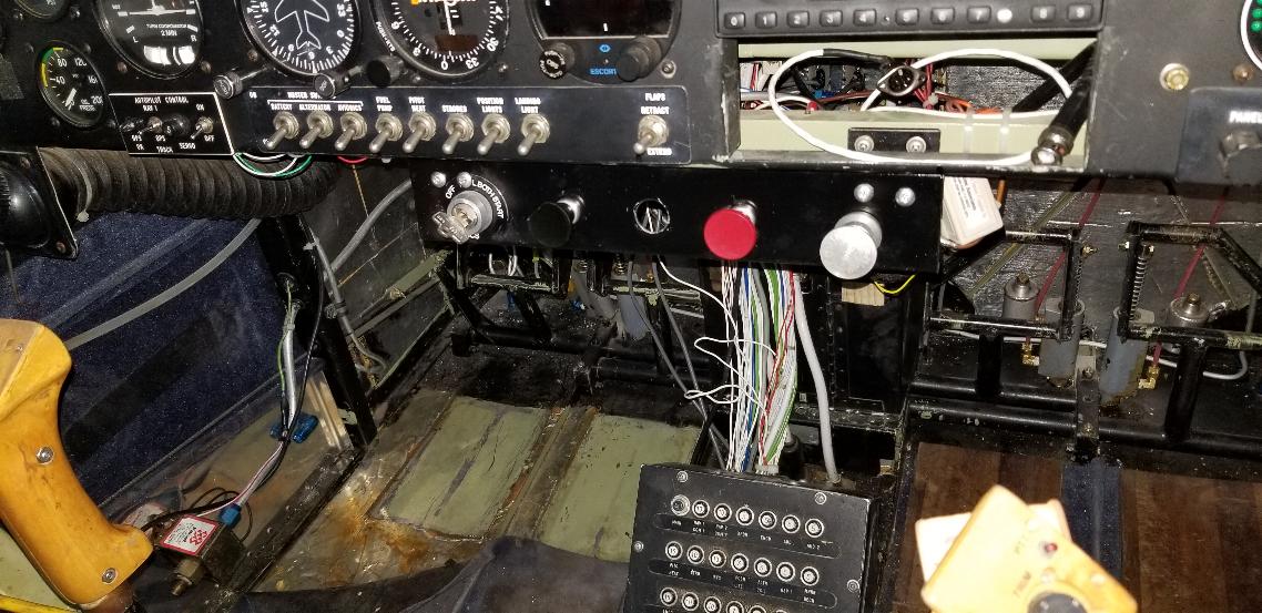
here's a panoramic shot of the panel. The question is, what do I
want to do with the panel? I am not a fan of the vacuum gyros and
vacuum system running from the engine. This also has the backup
vacuum system drawing from the engine manifold. I'm not a fan of
that either. I'm still mulling over a plan, but I'm thinking I
will get rid of the vacuum and backup vacuum systems, the vacuum pump
and regulator and replace it with a single 4" venturi in the turbulent
air on the belly behind the engine air outlet. I had a Stinson
configured that way and they worked great. I'm thinking I'll
remove the attitude indicator and replace it with either a Garmin G5 or
a Dynon D3. Right now I'm leaning towards the Garmin. The
Directional Gyro has a heading bug to drive the S-TEC Autopilot, so I'm
thinking I will keep it and run it off the 4" venturi. If the
Garmin G5 will share heading data with the S-TEC Autopilot, I'll
eleminat the Directional Gyro and be completely free of any vacuum
operated instruments. The Turn & Bank is electric and is part
of the autopilot controls, so it needs to stay. I do plan to
install a pair of USB ports on either side of the cockpit. Also,
I am not a fan of the vertical bar in the middle of the cockpit for
mounting the engine controls. I'll mount a horizontal piece below
the panel and will mount the engine controls to it. The Garmin
GPS dock will go away and I'll install a RAM mount there for my iFly
GPS. I'll need to make up a serial cable to go from the iFly to
the S-TEC Autopilot as it should be capable of being used as either a
wing leveler, slaved to the heading bug on the DG, slaved to the VOR,
or slaved to the GPS. We'll see how much of this I can get to
work once I get the plane back together and flying again. At this
point in time, I know the Push-to-talk buttons on the sticks don't
work. The panel lighting doesn't work. The aileron trim
doesn't work, but that issue has been found and parts are on order to
fix, and none of the trim or flap indicators at the top of the panel
seem to work. I'll play with them a bit and if it turns into a
problem, I'll replace the old MAC trim servos and indicators with the
newer Ray Allen servos and indicators.
Update: I decided to keep the vacuum gyros, but removed the
backup vacuum system that runs from the engine intake manifold. I
don't fly IFR, so if the vacuum system fails, it's not a crisis for me.
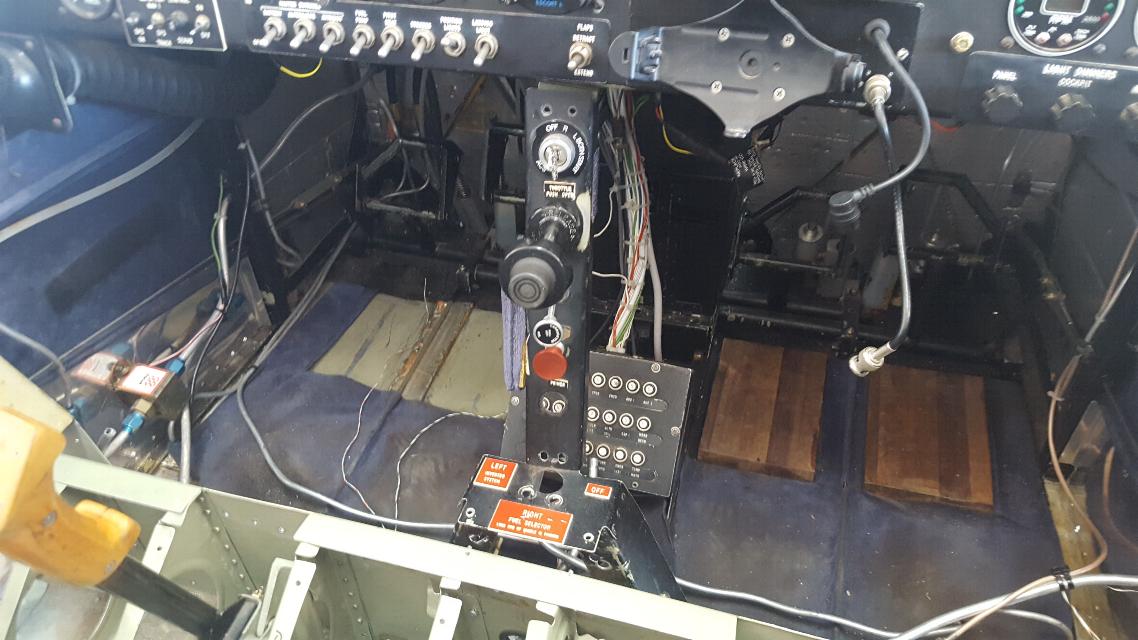
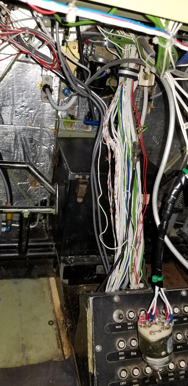
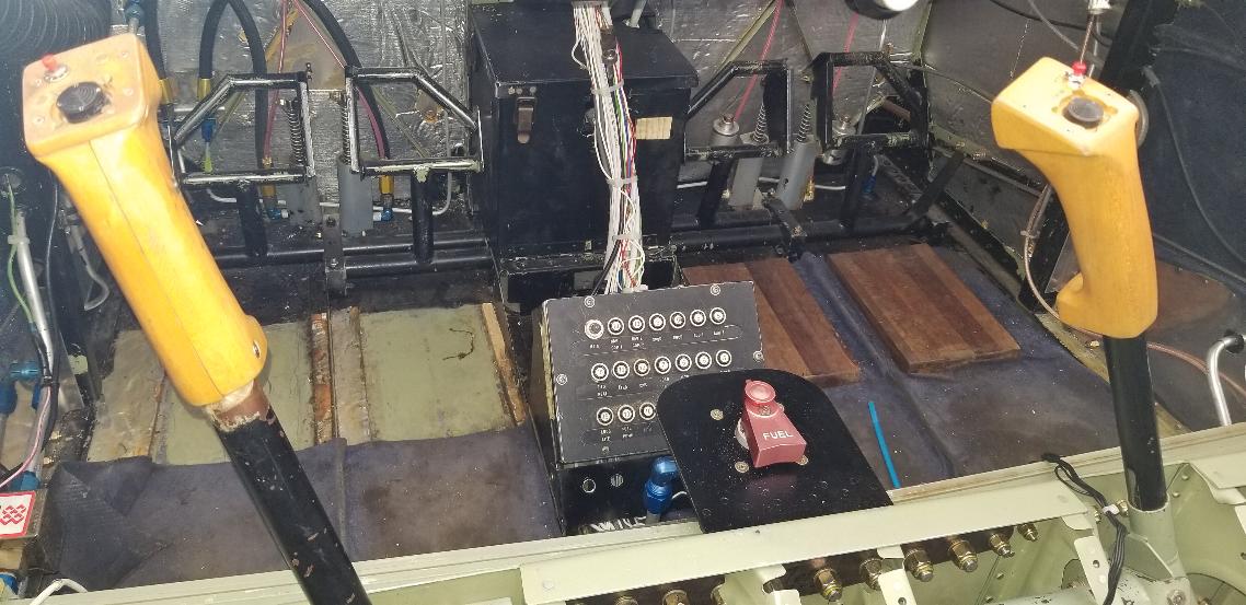
June 9, 2020 - today I pulled out all these fuel lines and brake lines,
the fuel selector mount, the vertical console where the engine controls
mount, and the Garmin mounting dock that's on the panel.
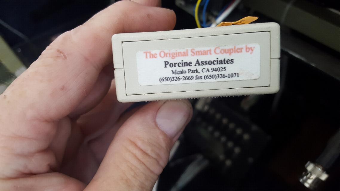
Behind the Garmin Dock, I found this coupler. I've never seen one
of these before, but after a bit or research, I found that it is a
coupler to interpret the serial output from the Garmin GPS to
the S-TEC Autopilot. I'll have to see if I can get this to
talk to the NMEA output from my iFly GPS. I ordered the iFly
serial cable and a breakout box for the plug. Hopefully I can
slog my way through this and get it to work.
The plan is to mount a horizontal panel to the bottom of the instrument
panel for the engine controls. I'll put a RAM mount for the iFly
GPS in front of the GPS to Autopilot coupler. Notice the fuel
selector panel, brake lines and most of the fuel lines are now missing.
I have an Andair fuel selector that I will install when I build a
new selector panel, probably after the wings are back on.
June 11, 2020 - Parts
arrived yesterday, so today I am working on the brake lines. I
replaced the leaky 1/4" nylaflow tubing from the passenger side to the pilot side with 3/16". Installed
bulkhead fittings for the brake lines to pass through the floor and
installed 3/16" 5052-0 AL brake lines. The long line that goes
from the right brake over to the right side was difficult to get in, so
I ended up cutting it in two and will add a flare coupling in the
middle. You can see the two female parts of the fitting above the
battery box in this photo. The AN815-3D coupler fitting had to be
ordered, so I can't finish this part until next week.
Right side brakes.
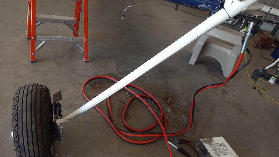
Fabricated the right side brake line to go from the bulkhead fitting
down to the brake caliper. The red and black cable under the
plane is a plug in 28V charger to keep the batteries charged up, or to
recharge as needed.
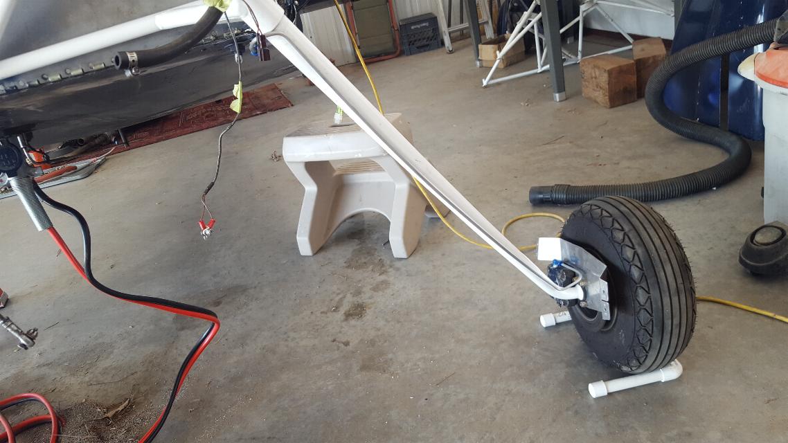
Fabricated the left side brake line as well. I'll add attachments
for these brake lines tomorrow. They will eventually be
underneath the gear leg fairings.
June, 13, 2020 - Flew the Cub to breakfast at Gastons this morning.
I added the fasteners to hold the Aluminum brake lines to the
gear leags. These zip ties are rubber lined, so won't chafe or
cut into the gear legs. The zip ties that act as a choke to separate
the line from the gear leg has heat shrink drawn down over the zip tie
to keep it from chafing.
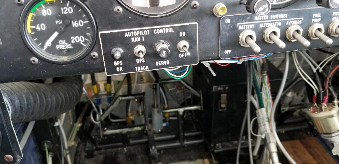
Not much to show here, but I had the autopilot control
panel out to replace the Nav1/GPS tracking switch as it was broken.
One more electrical problem hopefully fixed, a few more left to
go.
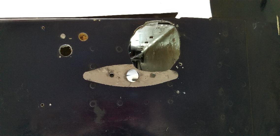
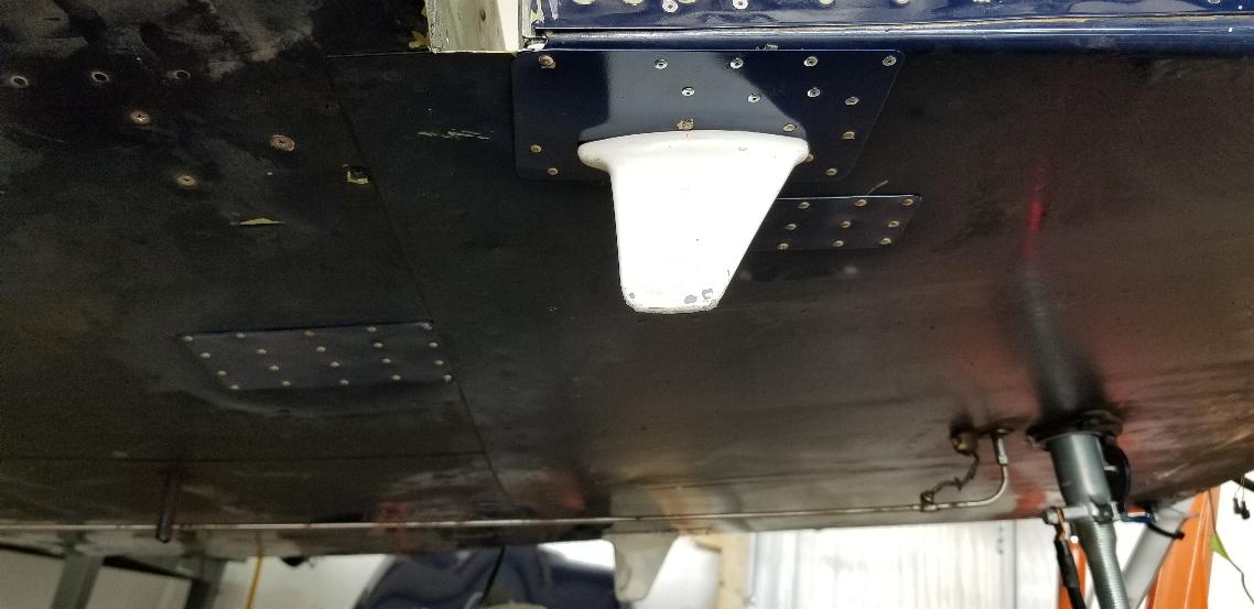
June 14, 2020 - This was the hole where the landing gear
exited the fuselage on the port side of the belly of the fuselage
during the short period this plane was configured as a tri-gear.
The hole to the left was for the brake line fitting, and the
oblong shape with three holes is where the DME blade type antenna used
to be. The same situation exists on the starboard side of the
fuselage as well with a transponder blade type antenna mounted over
there. These holes need to be repaired.
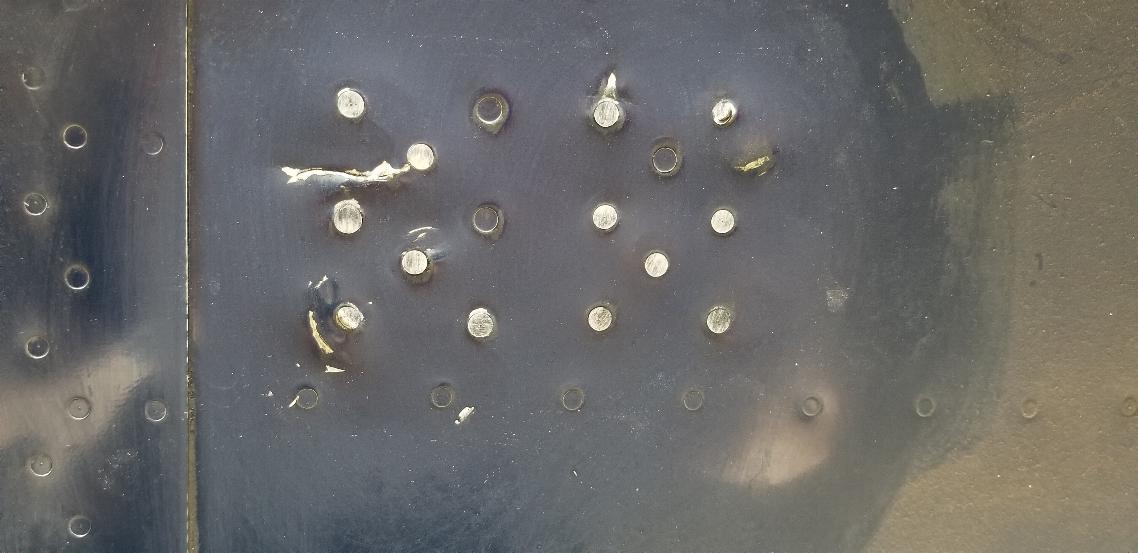
This is a really poorly done patch of some sort on the
belly.
There isn't a second piece of sheet metal there. Just these
overdriven rivets beat into the belly. You can see the skin is
cracked and these rivets were really beat in. The bucked side of
the rivets were smeared sideways, so they were also poorly bucked.
Kind of looks like someone tried to drive rivets with a muffler
shop air hammer rather than a rivet gun.
I drilled them out and will add a piece of .020" 2024-T3
Aluminum as a doubler on it.
I count 4 doubler patches on the belly. The gear exit holes
on both sides of the fuselage, the ugly mess in the photo above, and
another hole where a shop relocated the transponder blade antenna to
the middle of the floorboard where it was sure to get stepped on.
Once these patches are back on, I'll recut the holes for the DME
and transponder blade antennas and mount them up again.
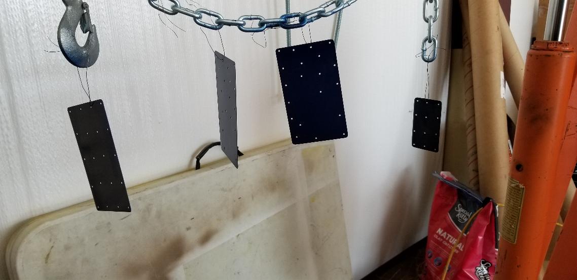
The patches have been alodyned, primed and painted, so are
ready to go on. All I need is a second set of hands to buck the
rivets.
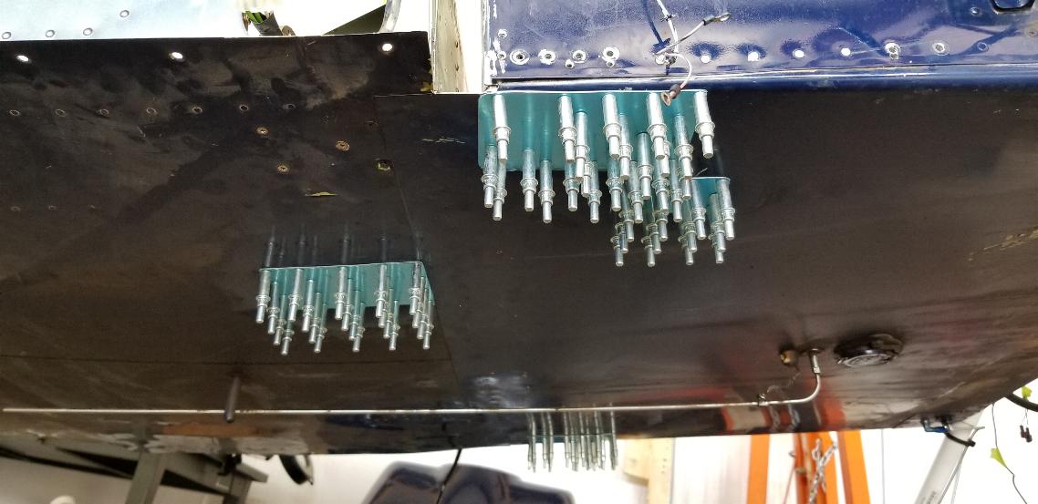
June 15, 2020 - Installed the painted doublers mostly with
clecos, and installed the blade antennae on both sides. You might
notice there are some pulled rivets in the near doubler plate.
There is no access to the back side to buck a hard rivet, so I
used blind rivets there. The same is true along the far edge
on the other side as well. The rest of the holes with the clecos
stuck in them will wait until I can draft a second set of hands to buck
rivets for me. The near blade antenna is the transponder and the
one on the far side is the DME (Distance Measuring Equipment) antenna.
Of course with a modern GPS on board, DME is now obsolete
equipment.
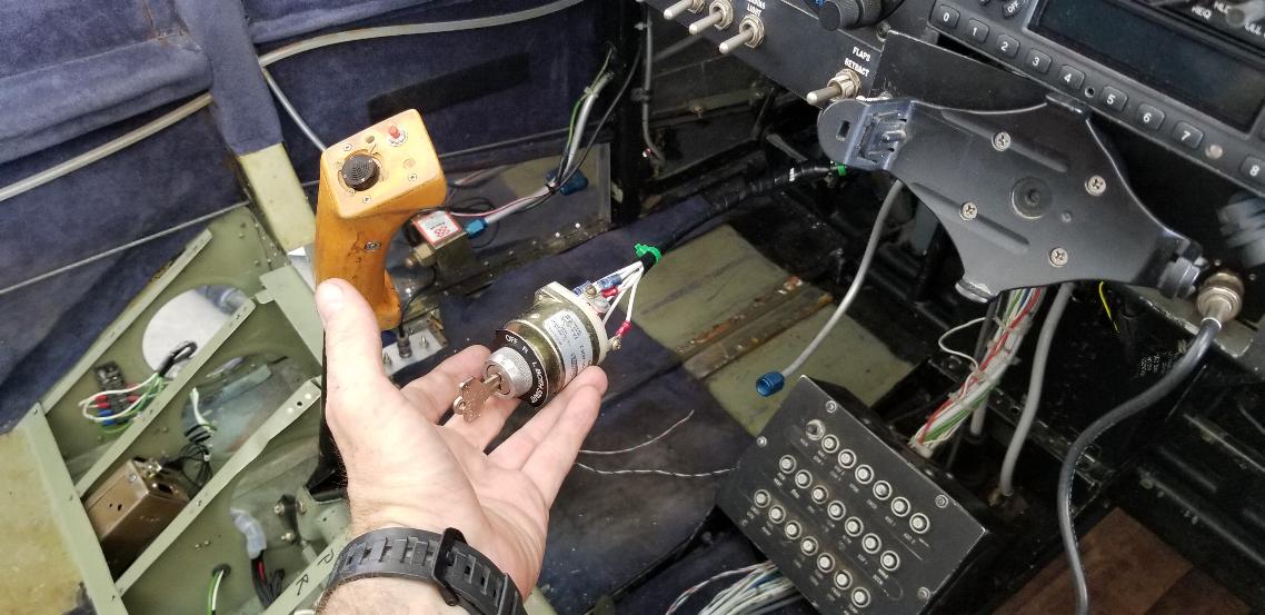
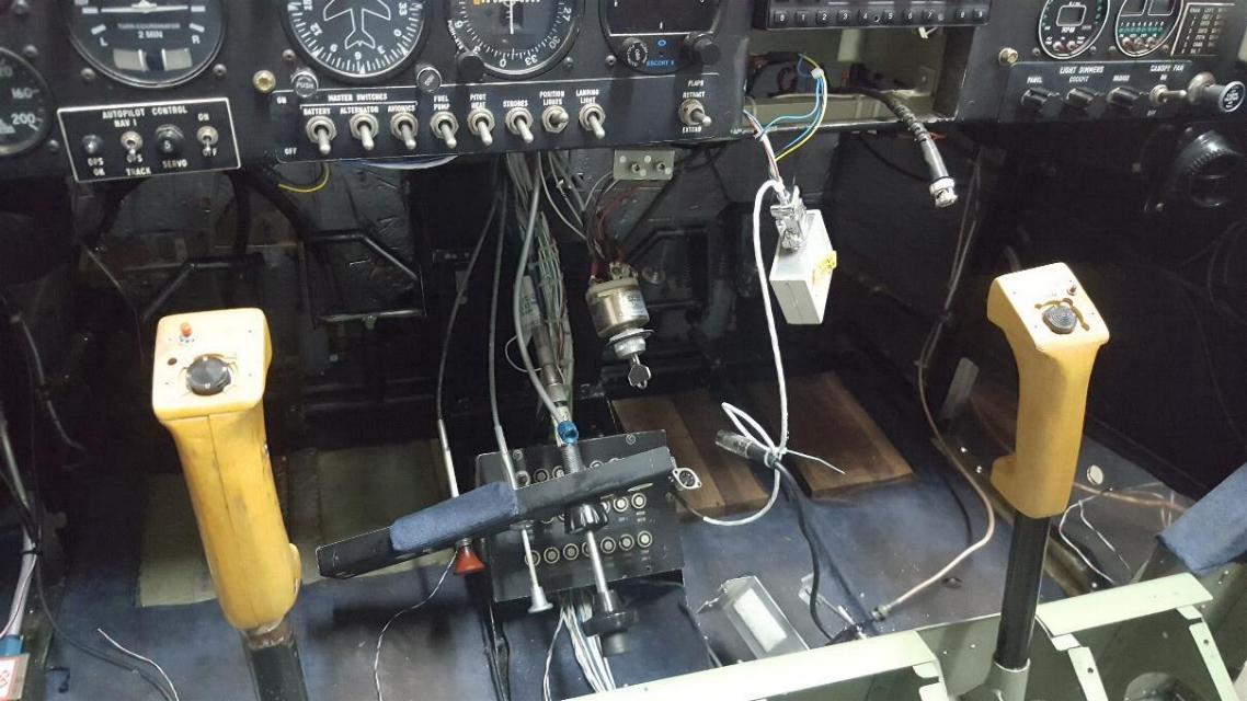
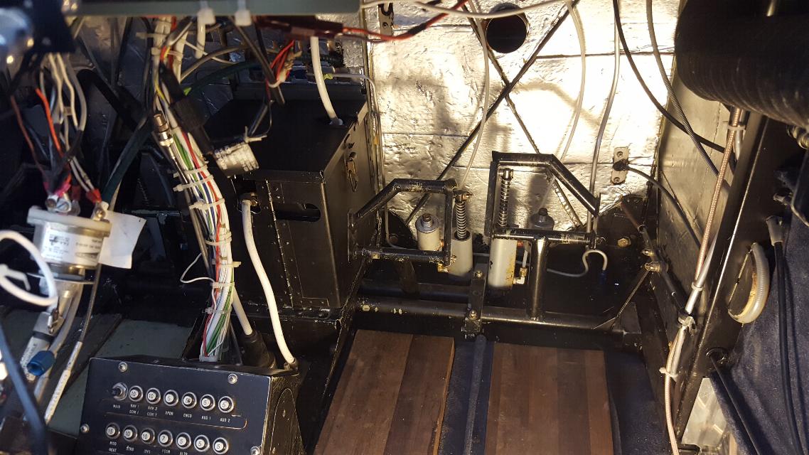
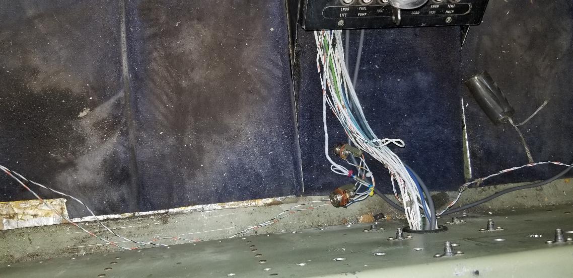
Reference the photos 12 and 13 photos above. The
center console is now gone and I extended the wiring for the magneto
switch so I can relocate it. I plan to mount a horizontal panel
under the instrument panel and will mount the mag switch, carb heat,
throttle, mixture, and maybe the primer in that panel. The Garmin
GPS dock in this photo will also go away in favor of a RAM ball mount
for my iFly GPS. You might also note that the engine control
cables are now missing. I have two of the cables ready to go in
when I get the mount for them fabricated, but won't see the
throttle cable for another month while ACS Products fabricates the
custom length cable.
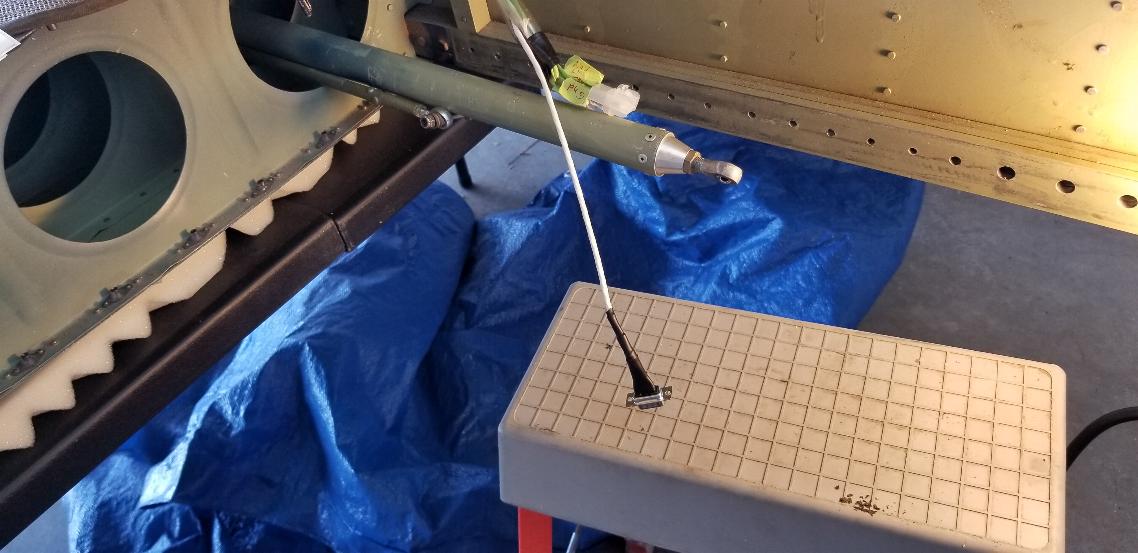
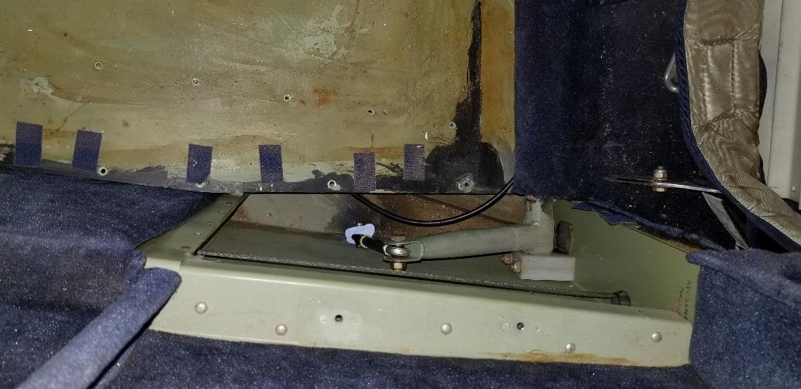
June 16, 2020 - The project of the day is the aileron trim
system. There were no disconnects to the wings when I
removed them, so had to cut the wiring to remove the wings. The
aileron trim was already broken before, so I also needed to chase that
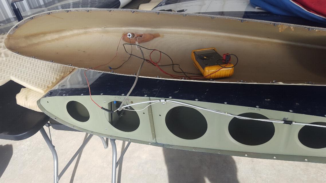
out. I was able to verify that the trim servo itself is
functional, and found that the wiring was torn out of the plug in the
wing tip, which was likely the source of the trim servo failure.
So, the small connector laying on the seat pan in this photo is
the new connector to attach the wiring from the wing root.
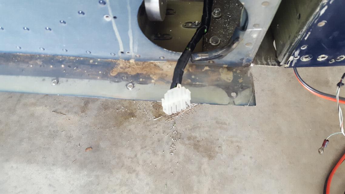
And here is the mate now ready in the wing root.
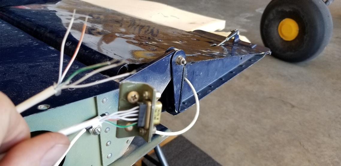
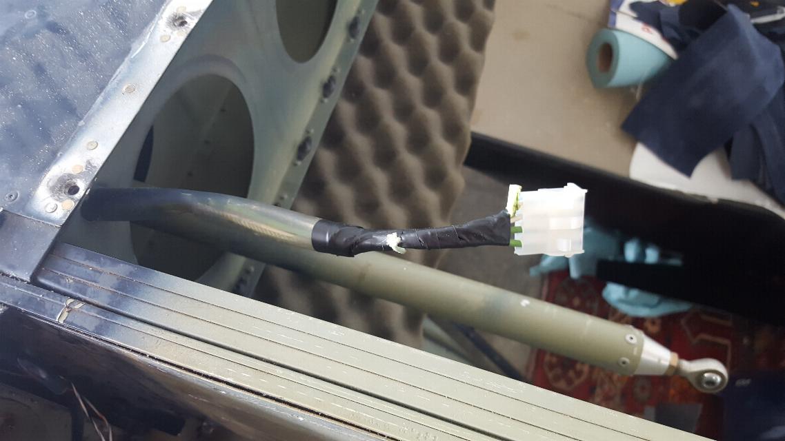
And this is the other end in the wing tip and the servo clearly present
in the aileron. I cut this connector off and replaced it as it
had some insulation cut and exposed wiring. The other half of the
connector on the trim servo will have to wait until I have the system
together as the wiring isn't fully marked or coded. So, I will
have to jumper it one way and see if the servo moves in the correct
direction or backwards to the input and wire it accordingly. The
same goes for the other three wires as they control the indicator
lights for the servo position, so I will have to trim to one position,
then touch the lighting wires to the teminals until the correct one
lights, then run the servo to the other end and touch the lights
to the two remaining wires to the terminals until the correct
position indicator lights. Then I'll only have one light and one
terminatl left, so hopefully that will be the middle indicator.
These are the old MAC trim servos and indicators, that are the
predecessor to the Ray Allen servos and indicators. The servos
are very much the same, but the indicator lights are a bit different
and consequently are wired differently. Fortunately, I still have
the wiring directions from when I wired the MAC servo in my KR some 24
years ago.
Update: I was getting nowhere with the mix of old servos and bad
wiring. I bought new Ray Allen servos and indicators and
installed all new further down on the page.
June 18, 2020 - I've spent the last two days frustrating myself with
radio and intercom issues. Voice from the intercom doesn't make
it's way to the radio. The PTT on the stick doesn't work, and the
aux jacks that bypass the intercom also didn't work. I found a
bunch of bad conections and skinned wiring for the intercom wiring, so
fixed that.
I replaced the bad connections with molex connectors. The
intercom seems to work just fine, but still doesn't talk to the comm
panel. These wires will get cleaned up and tucked away once I get
it working.
These are the Aux jacks that bypass the intercom. I found
multiple broken wires here. Once repaired, I can plug the
headset in here, and jumper the mic lead to trigger the PTT relays and
both comm radios successfully transmit with voice, so that's progress.
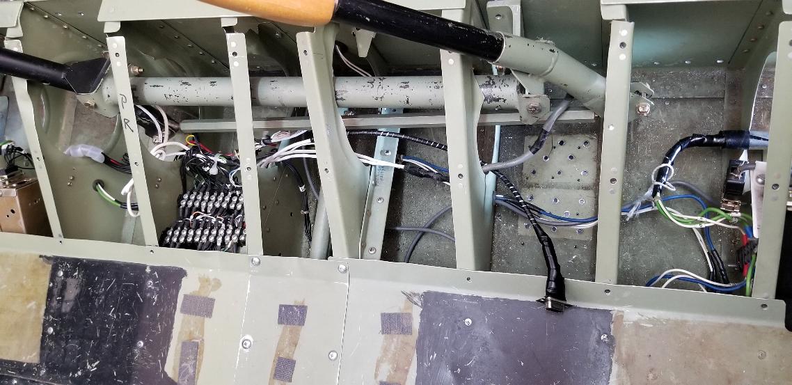
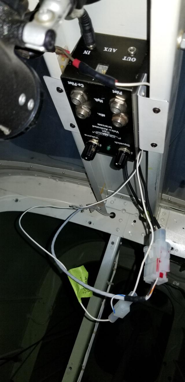
This is where I am headed tomorrow. The tie-in for
the intercom
is in the middle of this wire loom running up to the back of the NARCO
Comm panel. There's a failure somewhere between the molex
connectors I installed at the back of the intercom and the back of the
Comm panel. I should be able to trace it out tomorrow now that
this wire loom is opened up. I have verified that the intercom
works. I have verified that the comm panel and the radios work.
Now all I need to do is get them working together. Assuming
I can fix the intercom to
comm panel interface tomorrow, it will have taken 3 days to trace it
out and repair. I also need to trace out the PTT switch in the
sticks as that is also not functioning. That will also need to be
traced up through this same bundle of wires.
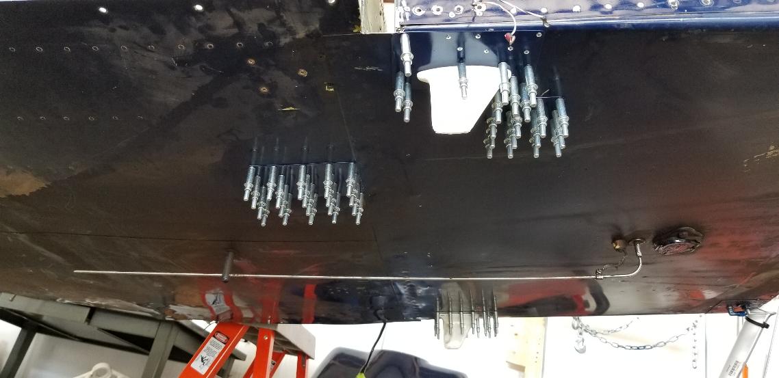
June 20, 2020 - My buddy Forrest from Oregon is here, so
crawled inside and bucked rivets for me. Now we have the 4 patches
riveted on.
June 21, 2020 - Today we fabbed up a couple of small panels. One
panel is mounted below the instrument panel and currently has the mag
switch, carb heat, and mixture controls in it. The two empty
holes are for the throttle in the center and the primer to the far
right. We also fabbed up the small panel just below the breaker
panel. The two holes there are currently designated for the Aux
headset jacks, which bypass the intercom. Or can be used to plug
in a portable intercom. Eventually, I may install a built in
intercom in this panel. For now, I'm still sorting out the
intercom/radio issues.
No picture to show for it, but we also pumped the brake systems full of 5606 hydraulic, so now the plane has brakes!
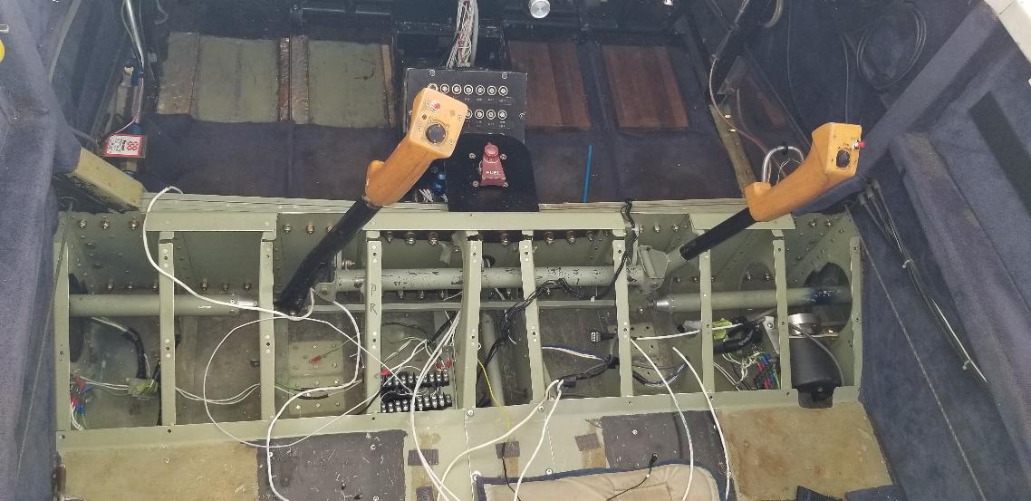
June 22, 2020 - It has wings again! Jim, Forrest, and Larry
helped me plug the wings back into the RV today. This thing may
turn into an airplane again one of these days. Thanks guys.
This stuff doesn't happen without friends.
We have all of the close tolerance bolts in that tie the two wings
together and anchor them to the airframe. We also have the front
and back bolts in that anchor the wing to the outside of the fuselage
and set the angle of incidence of the wings.. The wings are
stable now and no longer require support. We will reinstall the
rest of the spar bolts and bolt the control sticks back in
tomorrow.
June, 23, 2020 - All the bolts are in the spars... or so I thought.
Upon close examination of this photo, I found that I missed 4
bolts. There should be 76 bolts through the spar. But there
are only 72. I'll put in the other 4 in the morning before I move
on to the next task.
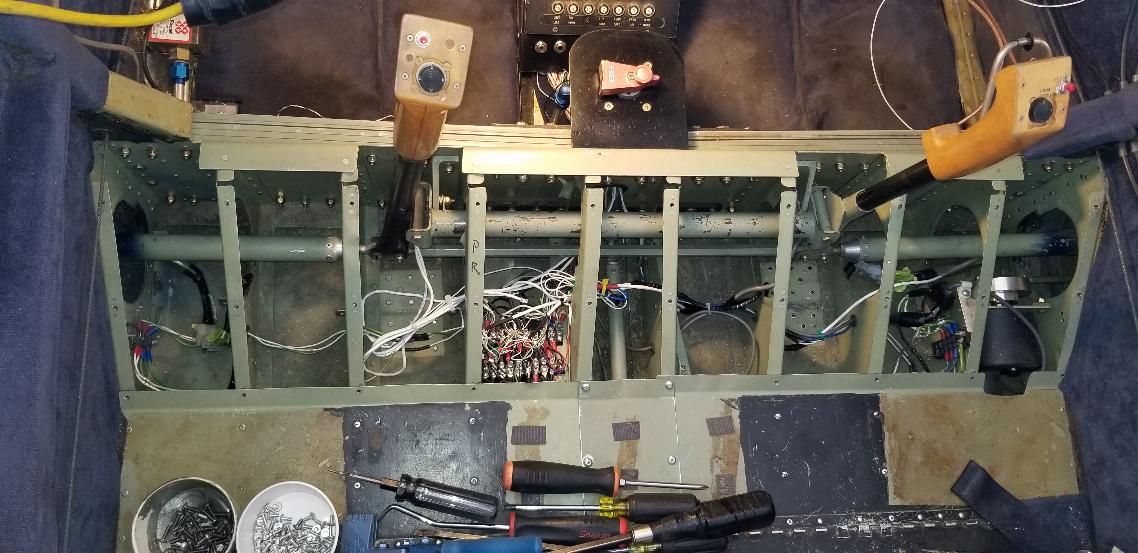
June 24, 2020 - Compare this photo to the one above. The ailerons
are now connected. The terminal strips are gone. The
mystery box and servo relays are also gone. We attempted to hook
up the aileron trim, but that was a no go. So, I decided to
replace the old MAC trim servos and the non-functional indicators with
all new Ray Allen servos, indicators and relay decks. All the
electrical junk under the seat turned out to be the elevator trim
system with indicators that don't work, the flap indicators that don't
work, the aileron trim that doesn't work, and the PTT switches that
also didn't work. So, it all came out and I'll sort it out as I
install the new gear.
Flaps are now connected. Even with all the electrical
junk missing from under the seats, the electric flaps still work.
We also ops checked the rest of the wing wiring. It's all
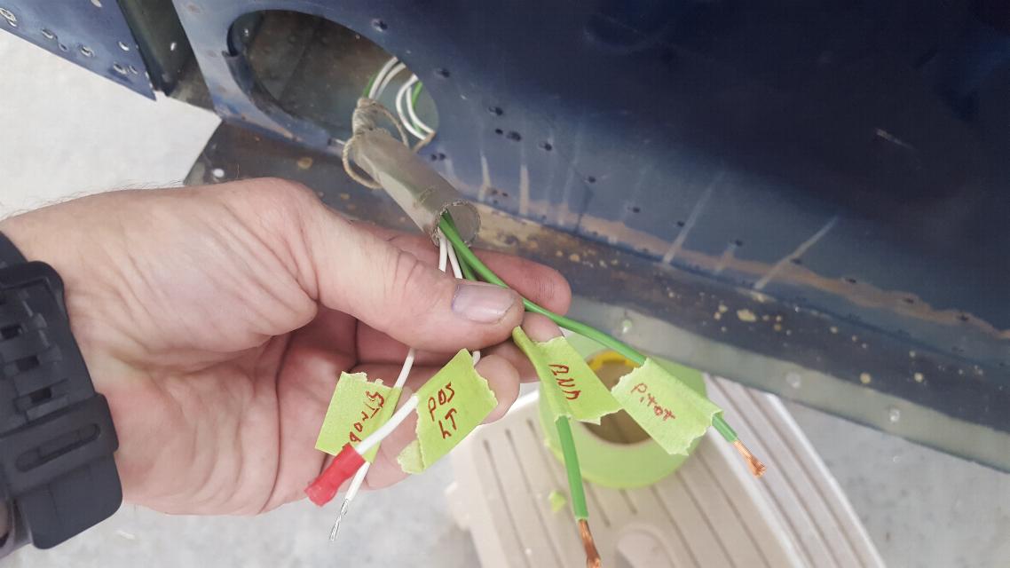
good. We've got pitot heat, position lights, strobes and landing
light.
External photo with flaps extended.
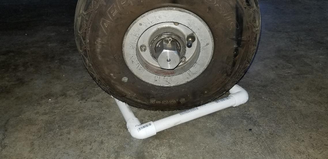
June 25, 2020 - I took my die grinder with a cutoff
wheel and put a cut into the axle stub so there would be a slot for the
cotter key to lock the axle nuts onto the axles.
I also added the primer and the primer lines to the throttle quadrant,
so it's installed and hooked up as far as in front of the firewall.
What's not showing is the fuel selector valve and
mount. The fuel selector mount is built, but not installed yet.
Additionally, the new throttle cable arrived today, so it will
also get installed tomorrow to complete the throttle quadrant. I
am replacing the brass selector valve with the somewhat ambiguous
pointer with an Andair fuel selector valve that I've had laying around
the hangar for a number of years.
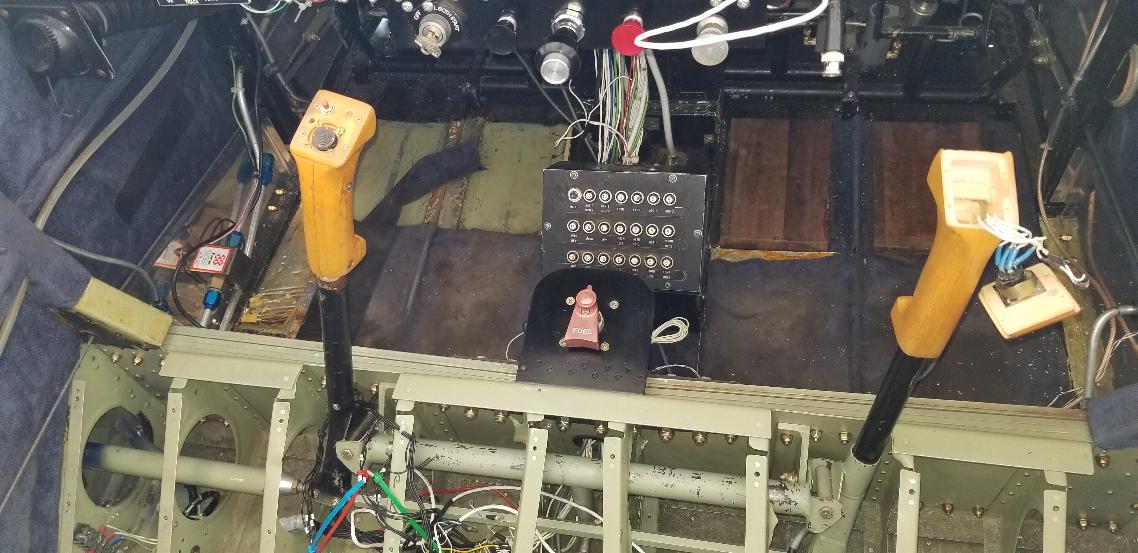
June 26, 2020 - This photo sums up much of today. We
installed the new fuel selector valve mount that we fabbed up yesterday
and the new Andair selector valve. I also fabricated new fuel lines
from the wing tanks to the fuel selector valve and a new line from the
selector valve to the fuel pump. I pulled the wiring from the
fuselage out to the fuel level transducers and hooked them up.
Notice the throttle cable is now installed in the throttle
quadrant, completing the quadrant Additionally, the new intercom
showed up yesterday, so I was able to test the new intercom with the
radios. Success! I removed all the old intercom
wiring and power and will install new with the new intercom. I
glued the rubber edges back onto the wing root fairings.
Everything is done in the wing roots, so the fairings should be
ready to go back on tomorrow.
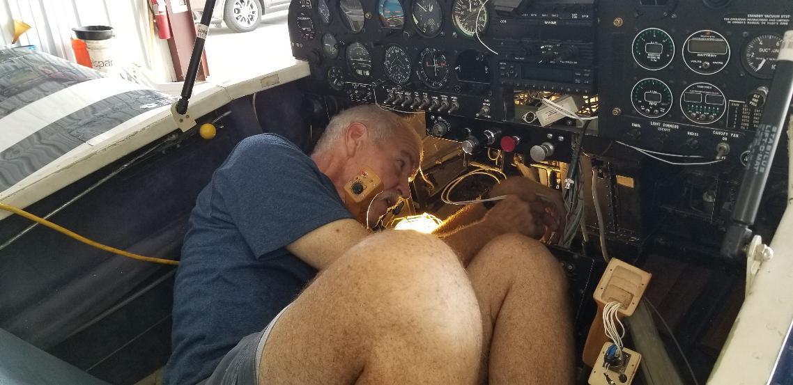
June 27, 2020 - Here's much of my day. Wadded up under the panel pulling wiring or zip-tying wiring.
For folks that know me, for many, many years, my weight was back and
forth from 285 - 300#. I now weigh 175#. The photo above
was a physical impossibility for me just a year ago; as was the energy
to take on this project.
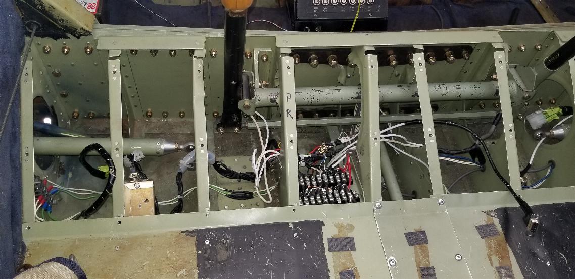
The terminal blocks are back in. I drew up a
wiring diagram for installation of the Ray Allen trim servos and
started on that. Not nearly the wad of spaghetti that was in
there before. Of course I'm not done installing stuff either.
I did a ring out of the stick wiring, so have it incorporated in
my wiring diagram. I'll ring out the servo wiring tomorrow and
will install the panel we fabricated for the trim indicators. The
servo relays are installed under the terminal blocks. The wiring
from the trim indicators is the two large loops laying on the seat, but
it's pulled down from the panel and the trim indicators are wired in.
NotiAt this point in time, all of the electrical is completed as
far as the front of the spar. One last electrical issue to chase
down is tha tthe post lights on the panel are not working. My
best guess without troubleshooting is that the rheostat for it doesn't
feel right, so that's likely the culprit. I'll have to chase that
down soon.
Note that the main wiring loom is now tied back
together and cleaned up. I forgot to take a picture, but we also
put the wing root fairings back on as everything inside of there is now
completed.
June 28, 2020 - Today we replaced the trim servos, did a ring out of
all the trim wiring, a lot of wire splicing, and built my own version
of spaghetti under the pilots seat. Those terminal strips are
where all the trim system (Pitch and Roll) tie in the indicators in the
panel, the switches in the sticks, the relays under the seat, and the
servos in the elevator and aileron. Now they are all functional
with indicators at the top of the panel. I still need to replace
the Aux headset jacks and wire in the new intercom, then I'm ready to
install the seat pans and put the forward cockpit back together again.
I am waiting for entry steps to arrive this week. We will
rivet them on in the baggage area of the aft cockpit, then will be
ready to reassemble the aft cockpit as well. I still need to
diagnose the problem with the post lights not working on the panel, and
do the tie in of the serial port from my iFly GPS to the S-TEC
Autopilot, but that should be the end of the tasks for the airframe.
Then it will be time to move on to the engine. Just another
week or so...
June 29, 2020 - No photos to show for today. I replaced the Aux
headset jacks and plugged the new intercom into the jacks. I ran
aircraft power to the intercom. Success! Now we have an
intercom and the ability to transmit over the radio using the PTT
switches in the top of the sticks. I drilled out the panels in
the baggage compartment in preparation for riveting on steps behind the
wings. I decided to attempt to diagnose the problem with the post
lights not working. That was narrowed down to the rheostat/power
supply. A new power supply is on order, so that should address
the issues with the post lights/panel lighting. Finding a
rheostat/power supply for incandescent lighting is getting to be quite
a challenge. If the new one fails, it may make more sense to
replace the post lights with LED lights and install a digital switching
LED controller. They are plentiful and inexpensive. I
cleaned up a bit more under the seat and now am ready to re-install the
seat pans.
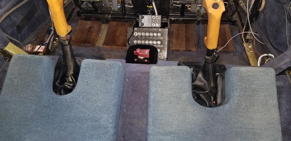
June 30, 2020 - For my buddy Oscar... One last
photo before I put the seat pans back in. It looks like spaghetti
in there again, but it's my spaghetti. I know how it is wired.
And I have a wiring diagram showing the wiring layout.
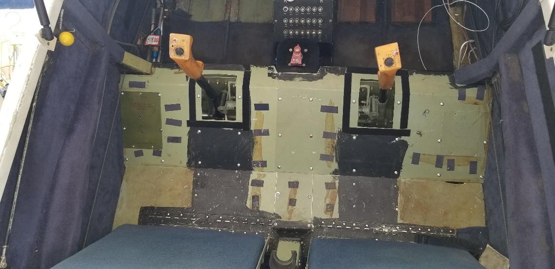
The seat pans are in now. I probably need to replace the velcro that keeps the seat cushions in place around the sticks.
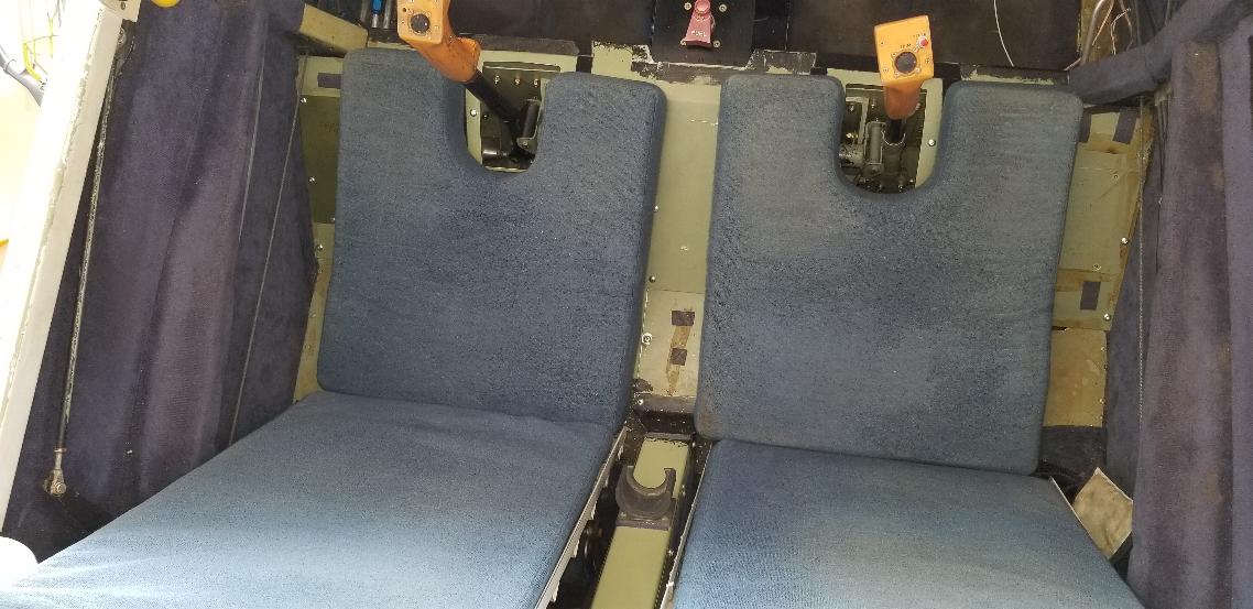
And the cushions are in. There was probably trim
or cushions of some sort between the seats and on the sides. I'm
thinking this interior may be kind of tired and will likely get
replaced anyway. Joni..., I have a job for you...
I also completed the panel below the transponder.
The face plate had a docking station for an older Garmin unit.
That was removed and a RAM ball mount was installed. Behind
that panel is the Porcine Smart Coupler that takes the NMEA output from
the GPS and converts it to an input for the S-TEC autopilot. I
spliced that input to the NMEA output from the iFly GPS, but have not
programmed the GPS to deal with it yet. The two stray wires
hanging over and under the panel on the right side will go to the
replacement power supply for the post lights on the panel and the
dimmer for the trim indicators. The power supply should be in
sometime in the next week. I have a different power cord with an
elbow coming for the GPS, so will have to change out the power cable.
I also only had one arm for the RAM mouint. I have an
articulated mount on order that will allow me to mount the GPS without
having it stick out so far from the panel.
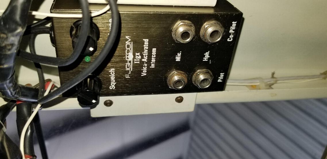
July 1, 2020 - The interior is in now. The
intercom is now velcro mounted on top of the breaker panel. It
wasn't until I looked at the photos that I noticed the piece of
interior missing on the upper left side of this photo. I know
exactly where that piece is laying, so will install it tomorrow.
Today, the entry steps arrived. I was hoping this would be a
simple one day job. Doesn't look like that will be the case,
although I should have everything cut, configured and ready to install
in a day or two. Then will have to paint the steps before they
get installed. I wish Vans had powder coated them white like they
did the landing gear and engine mount, but that wasn't the case.
Also, my buddy Oscar volunteered to have an overlay made for the
fuel valve. I was just going to label it with my label maker, but
Oscar couldn't stand me doing something so mundane. Thanks buddy.
Continued on Page 2
Engine on Page 3
Final Assembly on Page 4
Flight prep and test flying on Page 5
Comments or questions; Email me jscott.planes@gmx.com