The RV-6 Rebuild project
Page 4 - Finishing


February 
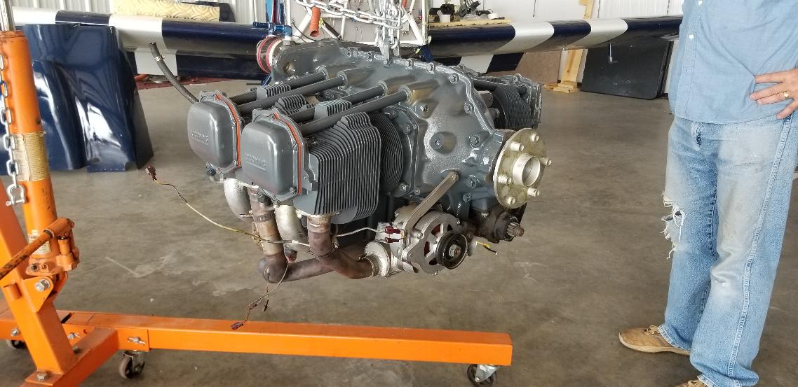
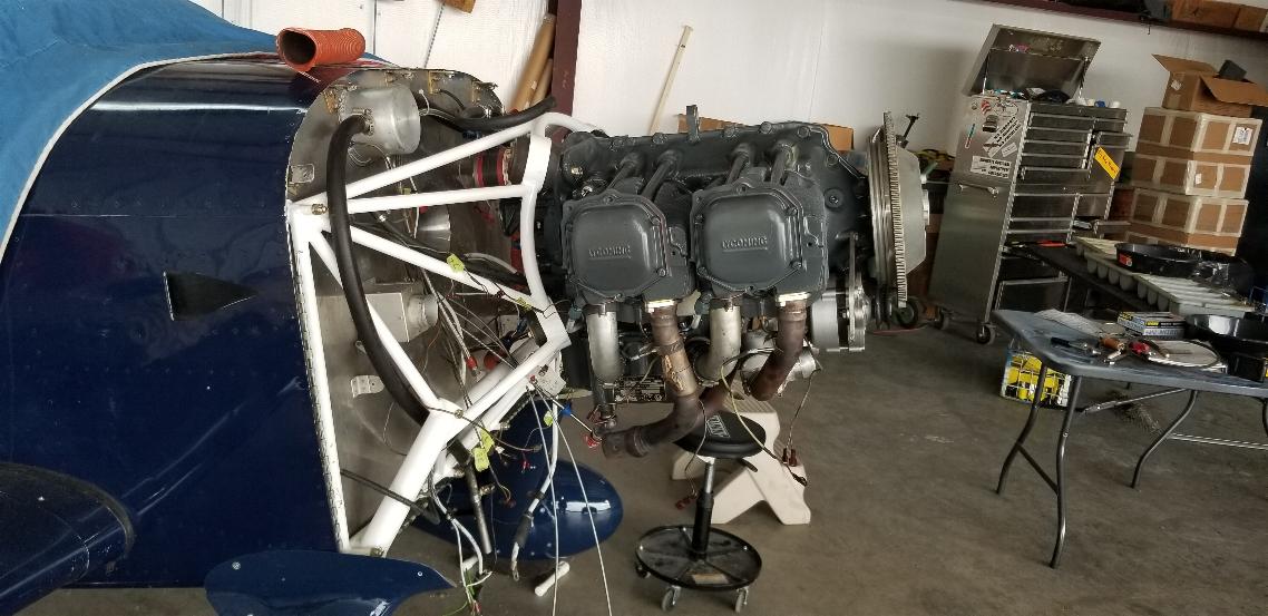
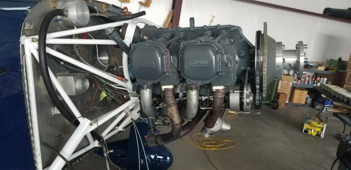
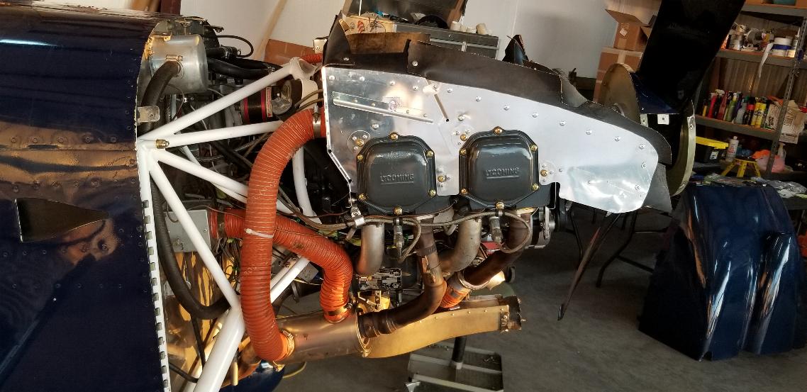
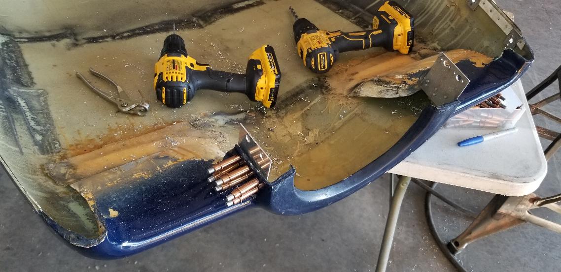
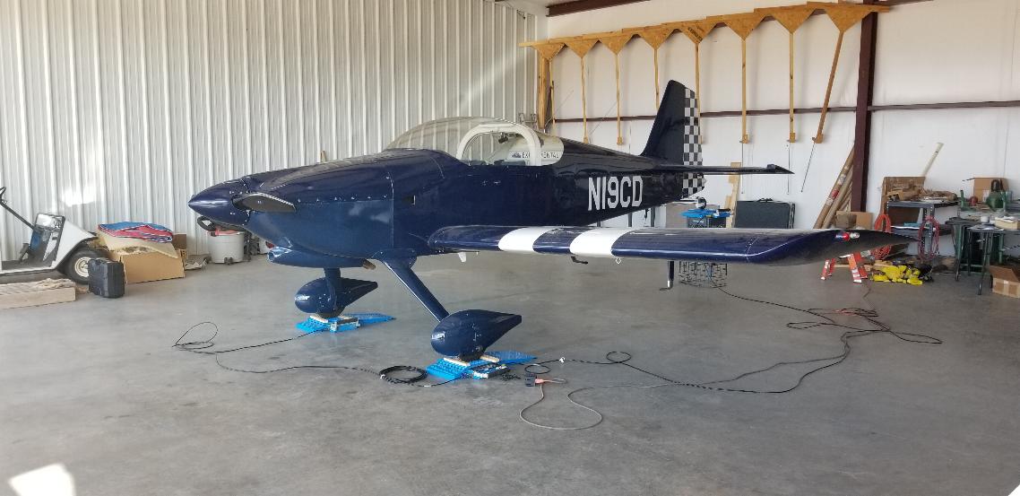
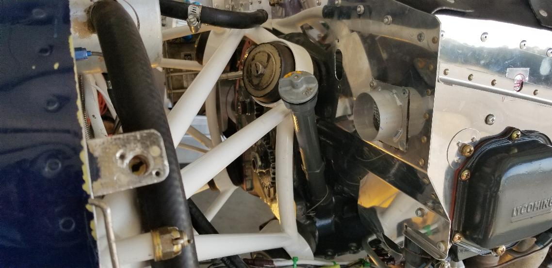
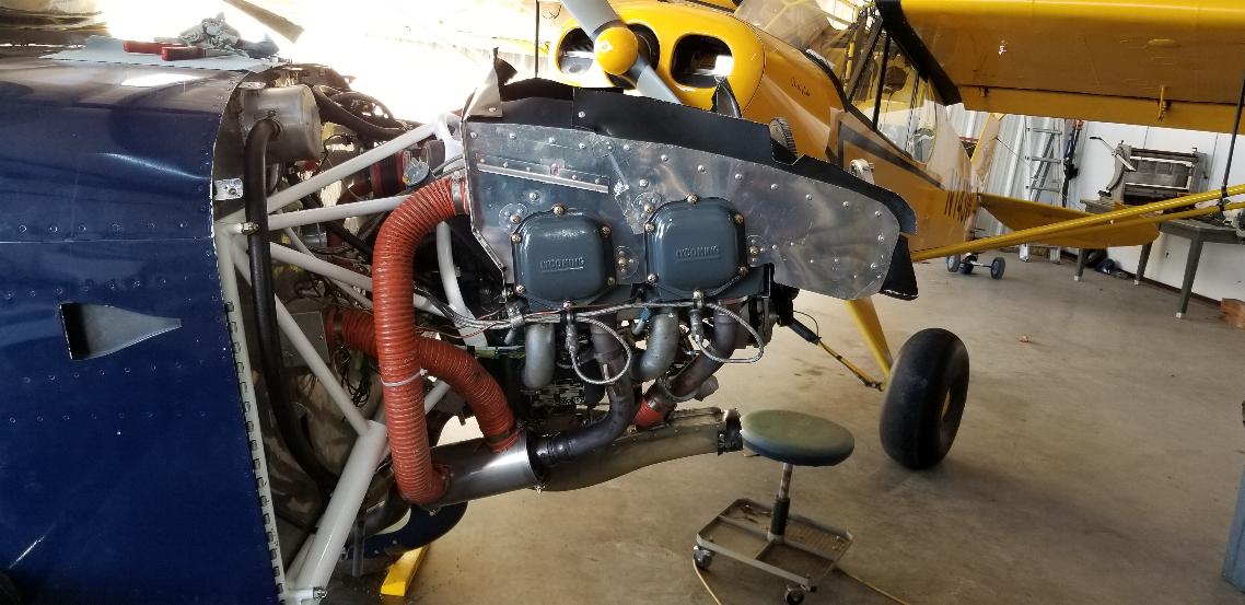
2020 - I ran across this RV-6 in Albuquerque, NM.   It has been damaged, but was priced about right, so I bought it.  Not sure if it was the right thing to do or not, but now I'm committed.  At first glance, it doesn't look too bad.  But then there are all the things I didn't know that I had to learn before I moved it.  


Return to Page 1
Return to Page 2
Return to Page 3
Go to Page 5


September 14, 2020 - The crank bolt finally arrived on Wednesday of last week, but we were leaving for the Light Sport Expo in Mt Vernon, IL the nextt morning, so I left it sitting on the table until today.  As I often times do, I got absorbed in what I was doing and failed to take any photo while finishing the assembly.  But, from the previous photos, all I did was install the bolt in the back of the crank, time the cam, install the accesory cover and oil pan, install the fuel pump, and install the vacuum pump.  And then we have what you see in the photo above hanging from the engine hoist.


Working on the dynafocal mounts.  With 4 long bolts all pointing in towards the center of the engine, dynafocal mounts can be a bit tedious to install.


The engine is now hung on the airframe.  I have a couple of days of work to hook up the controls, wiring, and plumbing.  


September 15, 2020 - Didn't get much done today.  Spent the morning dealing with an obstinate company (Lifelock) that's trying to screw with my mother's estate, flew the Cub to Gaston's for lunch with some friends from Kansas City, then flew the Cub to Calico Rock for Burgers & Brats this evening.  I did get the thermocouples all hooked up.  Then I hooked up the oil pressure line and found the pipe thread end of the fitting in the mirror above is not tight and sure to leak.  The mount is in the way so it can't be tightened.  (This might explain a lot of the oil scunge on the belly of the plane as I never took this fitting out of the accessory case!)  I'm going to have to at least loosen up the engine mount to get this fitting out.  I should be able to mount it where you see the hex head plug also in the mirror.  Sure wish I would have known about this problem while everything was out on the bench or on the engine stand.  Now the engine mount is kind of in the way.  I hope to get this fixed tomorrow, but will also be flying the Cub to Mountain View to meet another friend for dinner, so once again, work time is limited.  That's a lot of dining out for someone that really doesn't eat much.  It's a social thing.


September 16, 2020 - Compare this photo to the one above.  I have the plug out of the second hole and a plug in where the fitting was.  I could not get enough clearance to screw that fitting out without pulling the engine off the mount, so ended up cutting the top off the fitting with a die grinder and threading out the remains.  The plug was also really stuck in the hole I need to use.  I finally applied the propane torch to the case for a minute or two to warm it up enough that it finally popped loose without stripping the allen head.  I put a new plug in where I removed the fitting and ordered a new restricted flow fitting from Aircraft Spruce.


This just shows the cleanup of the wiring under the engine.  I really try to keep the wiring as tidy as I can and pull it down under the cylinders rather than the heads as cylinder cooling isn't terribly important.  But cylinder head cooling is critical.  Note that the starter also has the wiring connected now.


The same cleanup under the cylinders here.  I'll clean up the back as I get more stuff installed.  


September 17,2020 - What is this part?  This part is the mount for the throttle cable.  I replaced the original Vans supplied throttle cable with one that I liked better from ACS products.  So, of course, the cable didn't fit, or even mount in the same way.  I fabricated the U shaped collar to capture a slot in the throttle cable.  The two screws toward the right hold the slotted collar in place and the 1/8" plate at the bottom captures the bottom of the collar.


The throttle mount clamped onto the engine mount with the throttle cable mounted into it.


Carb heat control also connected.  Note the safety wire around the adel clamp on the cable.  Several wraps of .032  safety wire will wrap snugly into the grooves of the cable sleeve.  Putting a few wraps on either side of the adel clamp, then twisted tight ensures the cable sleeve won't slip in the clamp.  I did the same with the mixture cable as well.  Carb heat in this installation works by closing a flapper valve in the ram inlet of the airbox changing the air source to the heat exchanger just above the air box.


September 18, 2020 - After spending a couple of days working on other tasks while ruminating over how I want to build the baffling and where to mount the oil cooler, I decided to get started on it today.  The right side is really pretty much according to plans.  I still need to add a stiffener or two and the seal along to top.  Pretty straight forward and easy.


I finally decided to relocate the 7 vein oil cooler to the back of the baffling per the Vans plans.  It was previously mounted in front of #2 cyl requiring long oil lines strung over top of the cylinders.  It also had a small scoop to augment the air flow into the cooler.  But the insides of this engine was telling me the oil temp had been running a bit warmer than I want to see.  I had planned to use a 10 vein oil cooler, but it won't fit on the back side of the baffling due to interference from the engine mount.  Notice the dull colored baffling segment on #4 cylinder.  I fabricated this piece from stainless.  It seems that every RV baffle kit I see with the cooler mounted to the aft baffle has the baffling cracked around #4 cylinder.  This happened the first year after I finished the Cub as well (I used the RV baffle kit for it).  I fixed the Cub baffling by fabricating the baffle around #4 cyl from stainless.  Hopefully I've headed off the issue on this plane by using stainless around #4 cyl from the beginning.  Of course while cutting out this piece of stainless, I stripped the drive on my portable band saw.  I had to drive to Batesville to pick up a new band saw so I could finish the job.  That took a couple of hours out of my afternoon.  I expect the baffling will take another two or three days to finish.


September 19, 2020 - I've been thinking through the details about how to mount the oil cooler for the last couple of weeks.  Today it was time to get it on there.  It looks like so little to get accomplished for the day, but it was a lot of work cutting out the various little parts to reinforce the back and side of the baffling to support the oil cooler.  There is a .125" 6061-T6 Aluminum rectangular window frame under the oil cooler to reinforce the back plate.  There are two .125" 6061 Aluminum filler plates between the back panel and the side panel.  All of them needed to be custom cut and match drilled.  Sharp eyed observers will note the stack of 6 washers on the lower bolt mounting the far side of the oil cooler.  I needed to do that to keep the bolt from digging into the cylinder head fins on the other side.  I'll get a measurement and will need to order a shorter bolt to replace that one.

Most days at the airport are pretty quiet.  Today was filled with interruptions.  A few phone calls, friends stopping by to check on the project and a new friend that's a state trooper stopped in to see what I was up to.  He left with a promise for some time in the SuperCub tomorrow afternoon.  I really don't mind the interruptions and enjoy talking airplanes with anyone.

Tomorrow I can get a measurement for the oil lines and will get them ordered on Monday.  Not sure yet whether I'll have the local hydraulic shop make up some hoses for me, or whether I'll order the integral firesleeve teflon hoses.  I'm leaning towards getting the pricy teflon hoses made up for it.  I used them on the Cub and really like them.  I'll likely order a new fuel line of the same material as well.  It kind of depends on how tight the space is for the hoses.  The Teflon hoses are really stiff and can be difficult to install in tight confines where they need a tight radius bend.


September 21, 2020 - The last couple of days have been an exercise in patience and frustration.  It must have been a Friday afternoon when Vans packed this baffling kit.  It has extra pieces from other baffling kits in it (like an extra back to go behind #4 with a part number that doesn't belong in this kit) and is missing a lot of the small pieces (mostly brackets) that are supposed to be in the kit.  This is not the first time I've used the RV baffling kit, but this one seems to be significanly slower to build than the one I used 9 years ago.  I finally decided to set the plans aside and just build it with what I have and finish it with aluminum stock I have on hand.  I have been trimming the top of the baffling down little by little until it finally fits under the top cowl.  I have been adding braces and gussets here and there until it is now quite stiff.  Now I need to take it off and rivet it together, then add the chafe seal all around the edges. It will take another day or two to finish.  I took the measurements for the oil and fuel lines.  They are short enough with 90° bends that the Teflon integral firesleeve hoses are going to be too stiff to install in that short of a run.  I was going to have the local hydraulic hose shop make up the lines, but they use machine crimped aluminum ends on the hoses.  Those aren't commonly used in aircraft, so I'm a bit leary about installing them in mine.  So, I decided to order Airquip hoses, fittings, firesleeve and mandrels and will build my own.

The photo above is the front half of the baffling held together with Clecos at the end of the day today.  Maybe I'll be able to get started pounding rivets tomorrow.  I have had to fit the cowling on and off many times.  It would be so much easier if I had a second set of hands to help hold the cowling while I slide in the hinge pins.

Septermber 22, 2020 - Forgot to take photos today.  The summary is that I continued to work on the baffling, and will continue to work on it again tomorrow.  So, new pictures tomorrow.


September 23. 2020 - I took this photo just after starting this morning to make up for the lack of a photo yesterday.  I'm still piecing together the baffling.  It's just tedious work.


The baffling seems to be complete.  I added a 2" air pickup on the back right to feed the cabin heat and a 1" duct on the back left to duct cooling air to the gascolator.  


I also mounted and rough timed the magnetos, although I need to use the mag tweeter to dial them in yet.  I also have some cleanup to do on the baffling as I have a lot of notes and markings on the baffling written with a sharpie.  I have one more fitting and hose to install on the back of the engine and need to install a ground strap from the engine to the airframe.  I've really beat up the paint on the valve covers with installing and removing the baffling several times, so took them back off to repaint.


September 24, 2020 -  Not much to show visually.  I continued with the fit and finish on the baffling and the baffling to the cowling.  I think the baffling is now complete.  I put the tweeter on the magnetos and finished timing them.  I cinched up the bottom side of the baffling under the cylinders so the intercylinder cooling baffles are now tight to the cylinder and cylinder head fins.  They are tied with .041 safety wire.  I have all the ignition wires routed and hung with the exception of the two seen here hanging on the left side.  The prop extension is now torqued and safety wired.  The mufflers are now hung in place, although I still need to find and install the clamps to hold them on.


September 25, 2020 - The mufflers are now clamped on and heat exchanger for cabin heat is hooked up.   New spark plugs are installed and ignition leads are now routed and secured.  I also tidied up all the wiring under and behind the engine.


I fabricated the 3/8" fuel line and added firesleeve to it.  You can see it just below the oil cooler and above the left side muffler.


Looking down behind the engine.  You can see that the fitting for the oil line that goes to the oil cooler is still open and the oil filter has still not been installed.  I'll make up the oil hoses tomorrow, then install the oil filter.  Then the engine will be complete and ready to start.


Looking on from the front.  I pulled the prop through 4 blades.  The compression is certainly nice and tight.  That was enough to prime the oil pump as it promptly puked oil out through the oil filter housing onto the floor.  The fittings arrived for the 1/2" oil hoses today, so that will complete the engine tomorrow.  I'll plan to do the W&B on Monday, then will be ready to fuel and fire it up.


September 26, 2020 - I fabricated the lines to the oil cooler.  That should complete the engine install.  Just add fuel and it should be ready to fire up for a leak and functional check.


The previous owner re-used the same spinner after bending the prop and replacing it with a different prop.  Consequently, it has two sets of holes for the front bulkhead due to the different thicknesses of the props.  Add to that the poor workmanship of the holes, and I decided to fill and smooth over the holes, then will re-drill them.


Inside the spinner.  I filled the holes with epoxy resin and milled fibers, then laminated two layups of 5.8 oz tooling cloth on the inside of the holes.  The white patches you see in the photo is the peel ply over the wet layups.  I'll pull the peel ply in the morning and the spinner should be ready to drill new holes.  


I didn't like all the screws that hold the upper cowl on, so am converting to 1/4 turn camloc fasteners.  I drilled the holes out bigger to accept the camlocs.


I also drilled out the rivets mounting the nut plates so I can rivet in the camloc receptacles.  Of course the aluminum piece on the front cracked when I drilled it, so had to fabricate a new plate to mount the front receptacles.  And, of course, the rivet pattern for the receptacles doesn't quite match the pattern for the nut plates, so I will have to drill and countersink all new holes.  While I was drilling out one nut plate, the nutplate fell off and went right down the inside of the gear leg fairing, so I'll need to remove the fairing to get the nut plate out.


September 27, 2020 - The Camloc receptacles clecoed into place ready to be riveted on.


Camloc fasteners in the cowl.  I am short a half a dozen #10 length Camlocs to go across the back to fasten onto the boot cowl.  I bought enough to do it, but it turned out that 6 of the fasteners in the front of the cowl were one size too short   So the #10 fasteners got used there and I had to order 6 more for the back of the cowl.  I also finished the glass work on the spinner and installed it, but forgot to take photos.  I'll post them tomorrow.  We'll see what else crops up once I try to fire this up, but at this point in time, all I have left to do is the W&B then fire up the engine for a leak and ops check. Then once the logs are done, it should be ready to fly.


Spinner photo was added later.  You can clearly see the filled holes in the spinner.  Eventually, I'll fill again with micro-spheres and paint.


September 28, 2020 - Weight and Balance day.  It came out pretty good and is 18# lighter than it was when it was new.  I expect most of the weight loss was the weight of the damaged metal Sensenich prop that was on it being replaced by the wood and carbon fiber Prince Prop.

After completing the W&B, I rolled it outside and splashed some fuel in the tanks, then attempted to start it.  The batteries couldn't turn the engine through the compression stroke.  I put the batteries on the charger for the night.  We'll see if they can fire it up tomorrow or if I need to order new batteries.  Knowing the plane hasn't flown in many years, I expect I'll be ordering new batteries tomorrow afternoon.

September 29, 2020 - Nothing to show other than two useless batteries.  This plane has a 24V electric system using two Mor-Co AGM batteries sized and rated the same as the Odyssey PC-680 AGM batteries.  The date on the batteries is 8/18, so they are only 2 years old.  They appear to take a full charge, but are not sufficient to turn over the engine on the batteries even after spending the night on the charger.  I have two Odyssey PC-680 batteries coming, so it's unlikely I'll get to fire up the engine before this weekend.  Additionally, I found the electric rattle pump is not capable of enough lift when dry to pull fuel up to prime the system from a nearly empty tank.  The rating for this pump is a maximum of a 12" dry lift.  Note to self: Never run a tank dry since it can't pick up the prime from a low tank.


October 1, 2020 - Package arrived from Battery Mart.  No time to install batteries this afternoon.  Maybe I'll finally get to fire up the engine tomorrow.


October 2, 2020 - OK, batteries are in.  Time to light the fire...


WHAT IS GOING ON HERE???  Well, time for a confession.  When I ran the engine, it started and ran just great, for about 20 seconds.  Then it ran out of fuel.  I turned on the electric pump and started it back up.  The engine run went well.  No fuel leaks and no oil leaks.  However, as soon as I shut off the electric pump, I would lose fuel pressure.  Evidently, the mechanical fuel pump wasn't working.  I ordered a new pump, then removed the old one.  As soon as I had the pump out, the problem was obvious.  I had installed the pushrod that runs between the fuel pump cam and the fuel pump upside down.  As soon as I removed the pump, the push rod fell out of the accessory case and into the oil pan.  Not a problem to retrieve it, but the only way to install it properly is to remove the accessory case.  So, I removed the oil pan and accessory case.  The pushrod was indeed laying in the oil pan.  Of course I damaged the oil pan gasket when I removed the pan, so now I'll be waiting until next week to get in new pan and accessory case gaskets before I can reassemble.  Since I have a new fuel pump coming, I'll be installing it as well.  Maybe the first flight will be coming up next weekend.


October 13, 2020 - OK.  Time for more true confessions here.  Notice the gear with the cam on it in the photo above?  That cam is to actuate the fuel pump.  But, the gear is in the wrong place.  The idler gear with the cam for the fuel pump should be sitting between the crank and the camshaft.  Instead, it is sitting in the position of the idler that drives the prop governor, which is not installed on this engine anymore.

So, I had a few days of frustration after putting the engine back together with the idler gears swapped around.  It ran fine, but still no fuel pressure when I shut off the electric pump as there was no cam in place to run the fuel pump.  Of course I didn't realize that yet, so swapped the new fuel pump out for the old one, then found that it still didn't have any fuel pressure,  After reviewing the photos and some discussion with the local mechanic, it suddenly hit me.  Oh crap.  The idler gears are swapped into the wrong places.  So, I tore the engine back down to the status shown in the photo above.  In the photo below, you can see the idler gears in the correct positions with the cam for the fuel pump on the gear to the left.


This is the rod that was installed upside down.  There is a round cam follower head toward the right, which also keeps the rod from falling out of the accessory case.  But note that the top of the fuel pump rod is pointing at where the cam for it should be... between the crankshaft and camshaft, not below the crank as I had it configured.  This is stuff that is really obvious.  Makes me feel pretty dumb for making such a silly mistake.  But I have paid my dues for it with a week of frustration.


So, the oil sump accessory case, mags, both fuel pumps, and the vacuum pump are all out sitting on the bench again.  Everything is cleaned up and ready to go back together.  I need to move the fittings from the old fuel pump back to the new one and will install the new pump since I have it.  New gaskets will arrive tomorrow afternoon and I'll get started reassembling again on Wednesday.


October 14, 2020 - If nothing else, I've had practice taking this engine apart and putting it back together again, so am organized and reasonably quick about it.  Today I reinstalled the oil sump, the accessory case, the fuel pump, the vacuum pump, installed and timed the magnetos, installed the carb and intake tubes, reinstalled all the engine controls, oil lines, vacuum line, vent line and electrical connections, reinstalled the spark plugs and ignition harnesses, reinstalled the exhaust and reinstalled the dipstick tube.  Left for tomorrow is the oil filter, fill it with oil, cowl it up, and install the prop and spinner.  Unfortunately, the airport is closed while the runway markings are being repainted, and this weekend's weather isn't looking great for a first flight, so it may be next week before I can get this into the air.  But there is no reason to hurry at this point in time.


Octobrt 15, 2020 - It finally looks like an airplane again.  The things that are supposed to pressurize, suck, blow and pump are all doing what they are supposed to do.  So, now it's cowled up and ready for some ground testing, then flight testing.  The only notes from taxiing it this morning are that I was getting a high temp warning for #4 cyl due to the EGT and CHT thermomcouples being switched, and a low suction light despite the vacuum gauge showing good vacuum.  Those have been addressed, so now it should be ready for ground and then flight testing.


I did wash down the firewall and engine with solvent and scrubbed the belly.  Then I taxied it over to the maintenance hangar and washed it.  Once back in my hangar I wiped it down and detailed it.  At least we'll start out with it looking pretty.


Return to Page 1
Return to Page 2
Return to Page 3
Go to Page 5

Comments or questions;  Email me jscott.planes@gmx.com